Three run disk brake stack and method of assembly

a disk brake and three-run technology, applied in the field of multi-disk brake systems and aircraft disk brake systems, can solve the problems of limited thickness of available wear parts, and achieve the effects of increasing the longevity of individual disks, cost savings, and additional design flexibility

Inactive Publication Date: 2007-01-30
THE BF GOODRICH CO
View PDF34 Cites 10 Cited by
  • Summary
  • Abstract
  • Description
  • Claims
  • Application Information

AI Technical Summary

Benefits of technology

[0014]The brake stack includes, in addition to an end plate and pressure plate, rotors and stators. The end plate and pressure plate have only one wear surface, while rotors and stators each have two wear surfaces. The rotors are interleaved with the stators. The rotors, stators end plate and pressure plate are of three different sizes: a thick disk, a mid-thickness disk and a thin disk. The thick disks in the brake stacks are then subject to numerous landings and worn until they become mid-thickness disks, while the mid-thickness disks are worn until they become thin disks, and, the thin disks are worn to the minimum allowable disk thickness, at which time they are removed from the stack. At each overhaul, the fully worn thin disks are replaced with new or refurbished disks. By this configuration, a thick disk can go through three separate service runs prior to being replaced, where a mid-thickness disk can go through two service runs prior to being replaced and a thin disk can go through one service run prior to being replaced. If desired, at overhaul, following a service run, the disks can be moved to different positions within the stack or reversed. Alternatively, refurbished disks removed after a service run in a brake stack can be reinstalled in any stack, they do not have to go back to the same stack. Therefore, this unique configuration provides for increased longevity of the individual disks of the brake stack, while maintaining the same brake envelope. This provides a substantial cost savings for replacement of worn disks since only the thin disks are replaced at each overhaul.
[0015]Alternatively, the invention provides additional design flexibility to a brake designer. Where the brake envelope remains constant, the configuration allows an increase in worn heat sink mass and associated increased energy capacity while maintaining the same disk life as in prior known brake stack configurations. If size and weight considerations dominate the brake design constraints, the brake envelope can be reduced, using this inventive configuration to provide a more compact and lower weight brake assembly while maintaining the same disk life. Another alternative benefit of the inventive configuration is an increase in worn heat sink mass and associated energy capacity as well as increased disk life where the brake envelope and minimum disk thickness must remain constant.
[0017]In accordance with another aspect of the invention, there is provided a method of assembling a brake disk stack having disks with available wear portions of three different predetermined thicknesses. The disk(s) are subjected to a number of landings (based on the available wear portions of the disks having the least (thinnest) available wear portions) and then the brake stack is overhauled. At the first overhaul, the disk(s) having the available wear portions of a first thickness are approximately equal to disks having the initial available wear portion of a second thickness. The disks having the initial available wear portion of a second thickness are partly worn and at the first overhaul are approximately equal to the thickness of the disks having the initial available wear of a portion of a third thickness. The disks having an initial available wear portion of a third thickness, are substantially fully worn and at the first overhaul are replaced with new or refurbished disks of a first, second or third thickness, provided that the desired configuration of the brake stack is maintained.

Problems solved by technology

Due to the size and weight limitations on aircraft, the thickness of available wear portions is also limited.

Method used


Image

  • Three run disk brake stack and method of assembly
  • Three run disk brake stack and method of assembly
  • Three run disk brake stack and method of assembly

Examples


Embodiment Construction

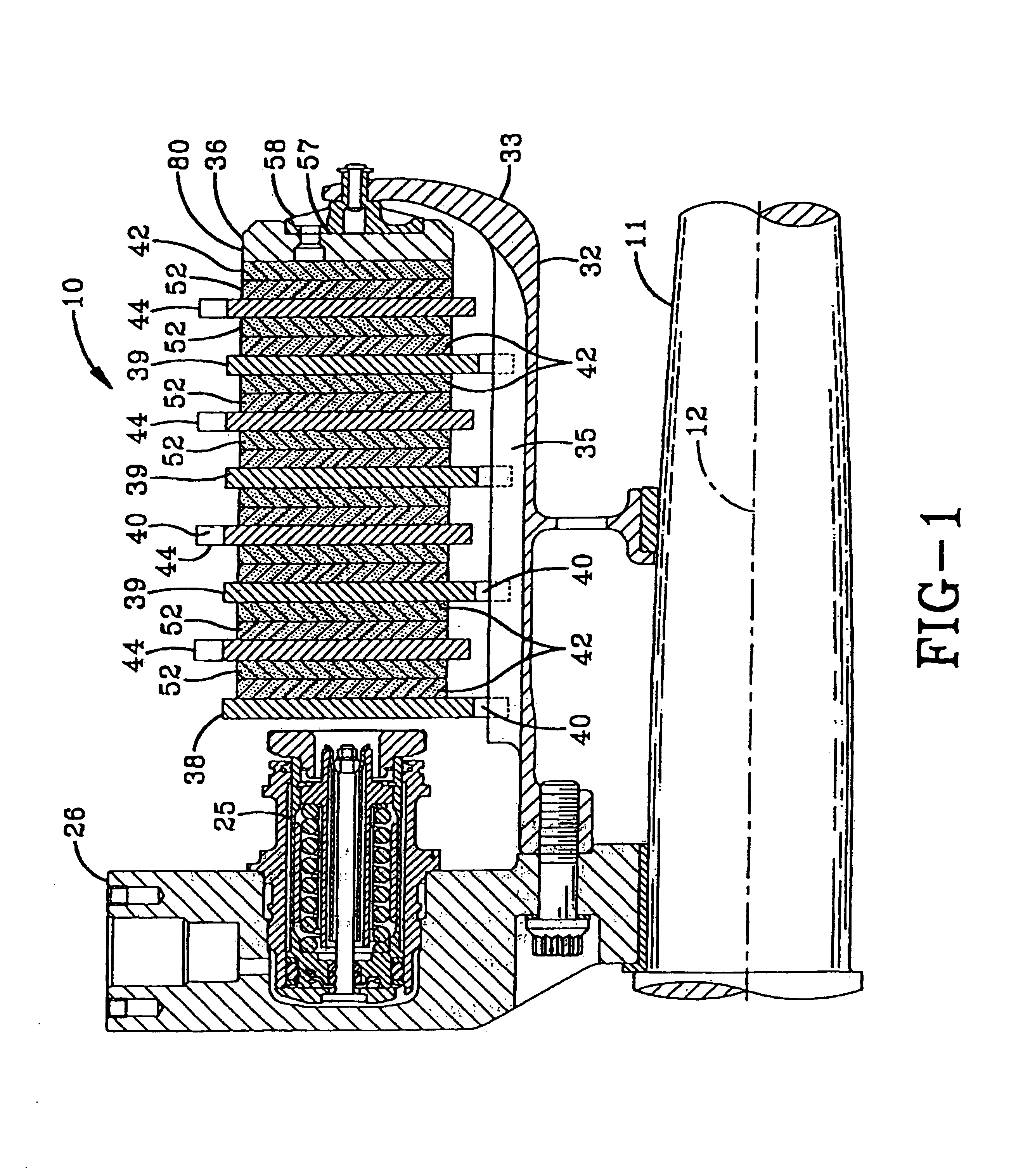
[0028]A friction brake mechanism 10 mounted on axle 11 for use with a cylindrical wheel rotatable about axial centerline 12 in a manner fully described in U.S. Pat. No. 4,018,082 to Rastogi et al., U.S. Pat. No. 4,878,563 to Baden et al., and U.S. Pat. No. 5,248,013 to Hogue et al. is shown in FIG. 1. The friction brake mechanism 10 includes a pressure plate 38 adjacent a thrust member, preferably a hydraulic piston 25, an end plate 36 distal from the pressure plate, and a plurality of interleaved rotor disks 44 and stator disks 39 which together form the brake heat sink or brake stack disposed therebetween. The friction brake mechanism 10 also includes a torque tube 32 on which the pressure plate 38, and stator disks 39 are slidably mounted against rotation relative to the wheel and rotor disks 44. End plate 36 is also mounted against rotation relative to the wheel and rotor disks.

[0029]Torque tube 32 includes a reaction plate 33 at its end, distal the thrust member piston 25. The ...


PUM


Abstract

In the invention there is provided a disk brake stack having disks with available wear portions of a first thickness, a second thickness and a third thickness. The disk(s) having an initial available wear portion of a first thickness are of a thickness so that at the first overhaul, the available wear portion of such disks are only partly worn away and disks are about equal to disks having an initial available wear portion of a second thickness. The disks having an initial available wear portion of a second thickness at the first overhaul are only partly worn away and such disks are about equal to the disks having an initial available wear portion of a third thickness. The disks initially having an available wear portion of a third thickness at the first overhaul are substantially fully worn and are replaced by new or refurbished disks having an available wear portion of a first, second or third thickness. Also, the invention comprises a method of assembly and overhaul of a disk brake stack, utilizing disks having available wear portion of a first thickness, a second thickness, and a third thickness.

Description

[0001]This application claims the benefit of provisional application No. 60 / 133,455 filed May 11, 1999.FIELD OF INVENTION[0002]This invention relates to braking systems. In particular, this invention relates to multi-disk brake systems used in vehicles. More particularly, this invention relates to aircraft disk brake systems. The brake disk assembly contains a brake disk stack, which comprises an end plate, a pressure plate and interleaved rotors and stators. The available wear portions of the rotors and stators have different wear thicknesses, so that the thickest disks in the stack are refurbished or replaced after three service runs. The mid-thickness disks are replaced or refurbished after two service runs and the thin disks are replaced or refurbished after one service run. Furthermore, this invention relates to a method of assembly of a disk brake stack having disks of different thicknesses.BACKGROUND OF THE INVENTION[0003]Aircraft brake systems have brake disk stacks comprise...

Claims


Application Information

Patent Timeline
Patent Type & Authority Patents(United States)
IPC IPC(8): F16D55/02F16D55/00F16D55/36
CPCF16D55/36F16D2055/0058F16D2250/0092F16D2250/00F16D2055/0095
Inventor BOK, LOWELL D.EDMISTEN, FRANK D.
Owner THE BF GOODRICH CO
Why Eureka
Try Eureka