Low power consumption adaptive power amplifier

a power amplifier and low power consumption technology, applied in the direction of amplifiers with semiconductor devices/discharge tubes, gated amplifiers, gain control, etc., can solve the problems of power amplifiers that sacrifice power efficiency at lower power levels, typical power amplifiers with less than optimal efficiency, and less efficient power amplifiers

Active Publication Date: 2007-01-30
GOOGLE TECHNOLOGY HOLDINGS LLC
View PDF11 Cites 107 Cited by
  • Summary
  • Abstract
  • Description
  • Claims
  • Application Information

AI Technical Summary

Problems solved by technology

Consequently, designing a power amplifier for high efficiency at high output power levels has generally resulted in power amplifiers that sacrificed power efficiencies at lower power levels.
However, the wireless device is generally only required to transmit at its maximum power level when the path losses are the greatest.
Consequently, typical power amplifiers have less than optimal efficiency most of the time that the wireless device is transmitting at low power levels since they were designed to operate most efficiently at high power levels.
As a result, when the power amplifier is using another modulation scheme, such as linear modulation, the power amplifier is less efficient.
As a result, if a power amplifier is optimized for linear modulation, the power amplifier will not provide high levels of efficiency when operating with non linear modulation.
However, turning off sections or removing the bias signal from sections of the final stage amplifier affects other parameters of the power amplifier, such as the optimum output current and voltage operating region, power amplifier loading, and power amplifier output impedance.
As a result, this technique alone does not provide optimal performance for minimizing power consumption at low power levels.
However, there is a limit to the amount that the bias signal can be reduced.
Reducing the bias too much will lead to distortion, and therefore increase the likelihood that spurious signals will enter adjacent channels in the communication system.
Further, the distortion may negatively affect the ability of a base station receiver to detect the incoming signal from the wireless device transmitter.
However, this technique does not provide optimal efficiency for minimizing power consumption.

Method used


Image

  • Low power consumption adaptive power amplifier
  • Low power consumption adaptive power amplifier
  • Low power consumption adaptive power amplifier

Examples


Embodiment Construction

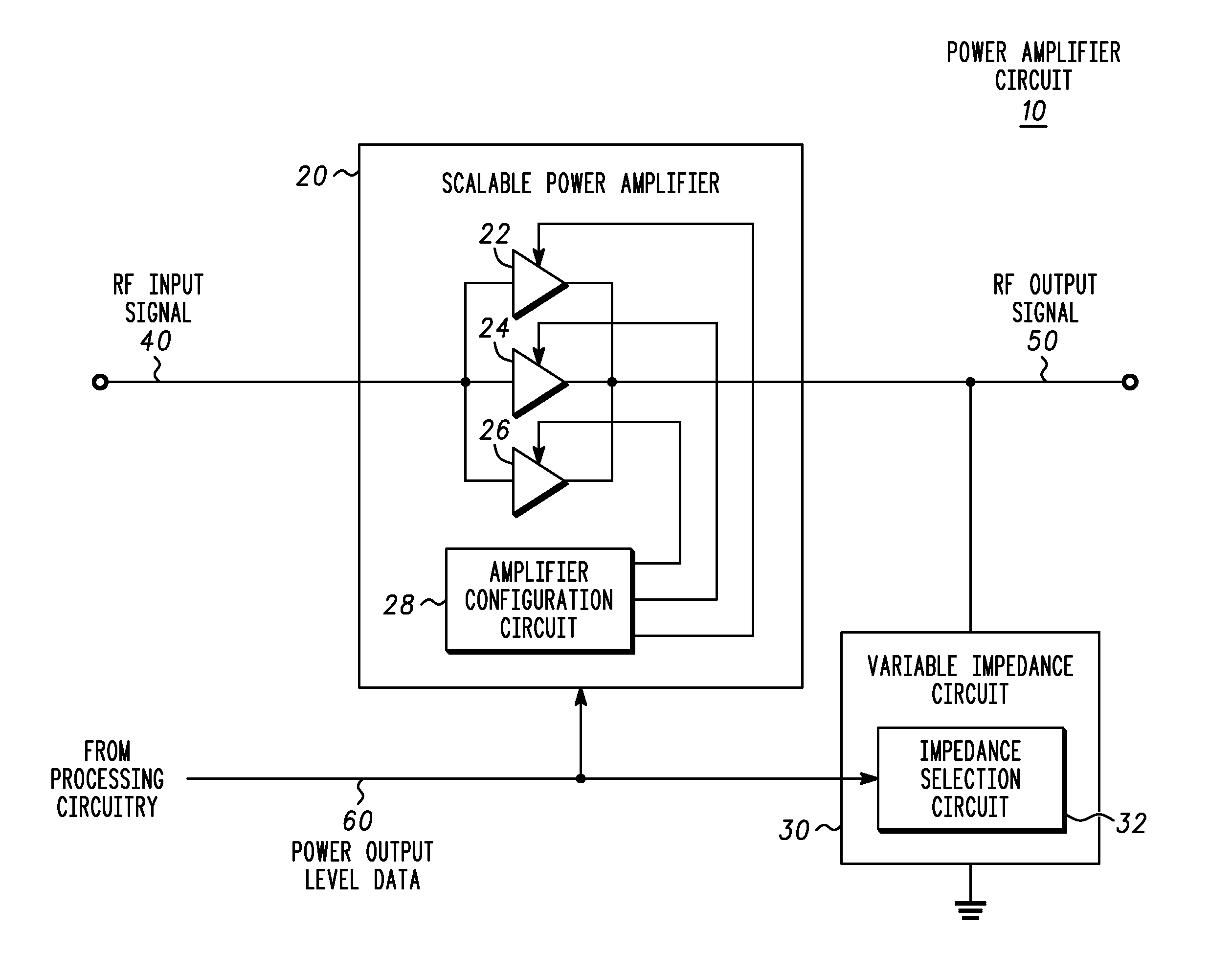
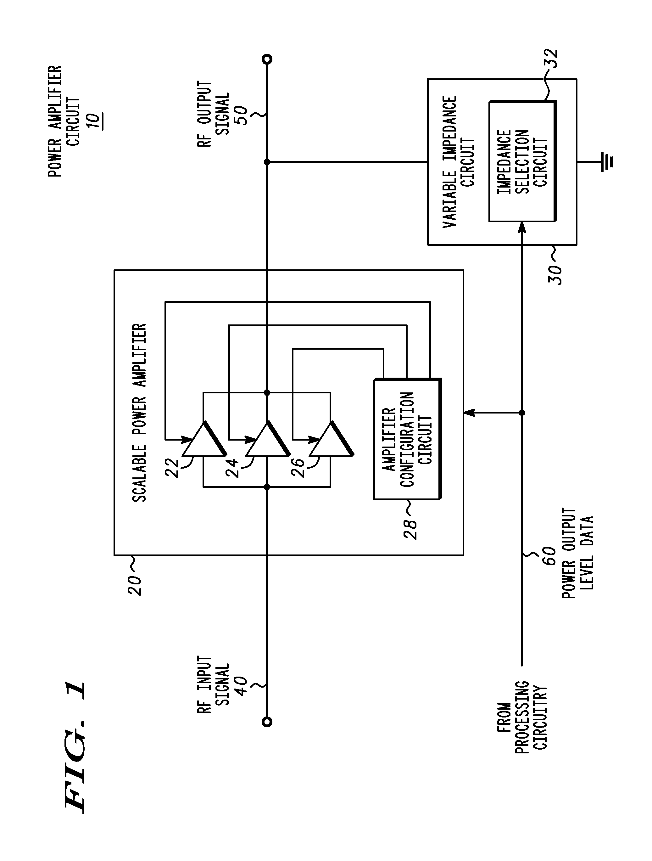
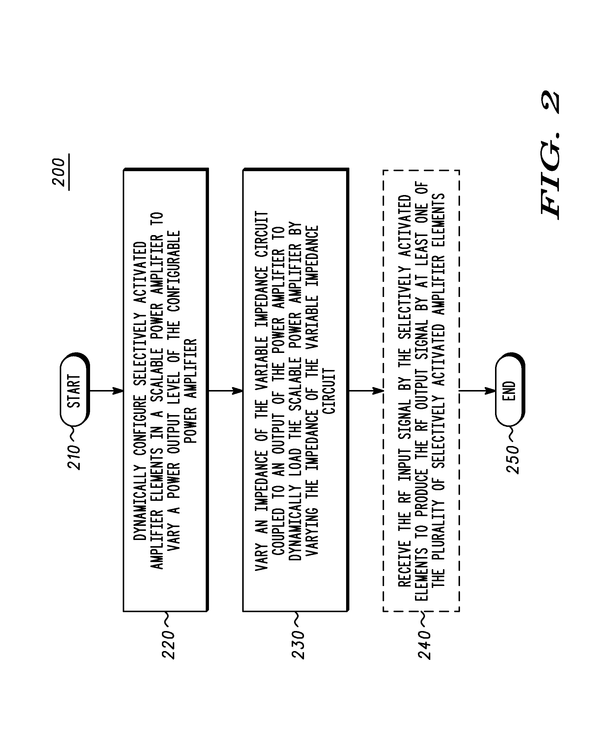
[0020]A power amplification circuit includes a scalable power amplifier to produce an RF output signal at an output of the power amplification circuit, and a variable impedance circuit coupled to the output of the power amplification circuit. The scalable power amplifier includes a plurality of selectively activated amplifier elements to produce the RF output signal in accordance with a desired RF output signal power level. The power amplification circuit selectively activates individual amplifier elements by, for example adjusting the power supplied to the individual amplifier element, and selectively decoupling the RF input signal to at least one amplifier element. The variable impedance circuit varies an impedance of the variable impedance circuit to dynamically adjust the value of the load coupled to the output of the scalable power amplifier

[0021]If the required RF output signal power level decreases for example, then individual amplifier elements may be selectively deactivated...


PUM


Abstract

A power amplification circuit (10) includes a scalable power amplifier (20) to produce an RF output signal (50) at an output of the power amplification circuit (10), and a variable impedance circuit (30) coupled to the output of the power amplification circuit (10). The scalable power amplifier (20) includes a plurality of selectively activated amplifier elements (22), (24), (26) to produce the RF output signal (50) in accordance with a desired RF output signal power level. The power amplification circuit (10) selectively activates individual amplifier elements by, for example reducing power or increasing power to at least one amplifier element. The variable impedance circuit (30) varies an impedance of the variable impedance circuit (30) to dynamically load the output of the scalable power amplifier (20).

Description

RELATED APPLICATION[0001]This application is related to a co-pending patent application Ser. No. 10 / 272,964, to Klomsdorf, et al., entitled “Power Amplification Circuit and Method for Supplying Power at a Plurality of Desired Power Output Levels,” filed on Oct. 17, 2002, which is assigned to instant assignee.FIELD OF THE INVENTION[0002]The present invention relates generally to a power amplifier circuit and more particularly, to a power amplifier circuit for providing an RF output signal at a plurality of desired power output levels.BACKGROUND OF THE INVENTION[0003]Many wireless communication protocols provide for transmitters, operating within a communication network, which are capable of transmitting at varying levels of output power. One reason for having varying levels of output power is to accommodate transmitters in wireless devices such as wireless telephones, wireless personal data assistants (PDAs), pagers, two-way radios, and other types of wireless devices, which may be l...

Claims


Application Information

Patent Timeline
Patent Type & Authority Patents(United States)
IPC IPC(8): H03F1/14H03F1/02H03F1/56H03F3/21H03F3/72
CPCH03F1/02H03F1/0211H03F1/0261H03F1/0277H03F1/56H03F3/72H03F3/211H03F2203/7227H03F2200/303H03F2200/391H03F2200/417H03F3/20
Inventor CONRAD, CLARKKLOMSDORF, ARMINSCHIRMANN, ERNEST
Owner GOOGLE TECHNOLOGY HOLDINGS LLC
Why Eureka
Try Eureka