Filter device capable of obtaining attenuation characteristic of sharpness in narrow band width and branching filter using the same

Active Publication Date: 2007-01-30
SNAPTRACK
View PDF18 Cites 8 Cited by
  • Summary
  • Abstract
  • Description
  • Claims
  • Application Information

AI Technical Summary

Benefits of technology

[0043]Subsequently, the branching filter becomes capable of obtain

Problems solved by technology

In addition, the filter device has not only pressure temperature dependence that temperature of the filter device varies characteristics thereof but also individual difference due to unevenness of manufacturing the filter device.
However, in the above-described conventional technique, especially when the pass-band and the cut-off band become

Method used


Image

  • Filter device capable of obtaining attenuation characteristic of sharpness in narrow band width and branching filter using the same
  • Filter device capable of obtaining attenuation characteristic of sharpness in narrow band width and branching filter using the same
  • Filter device capable of obtaining attenuation characteristic of sharpness in narrow band width and branching filter using the same

Examples


first embodiment

[0068]Now, referring to FIGS. 4 through 13, description will proceed to a filter device according to the present invention.

[0069]FIG. 4 is an equal circuit diagram for schematically showing a constitution of the filter device according to the first embodiment of the present invention FIG. 5 is an explanation view for schematically showing a constitution of an SAW resonator as an example of a resonator used in the filter device illustrated in FIG. 4. FIG. 6 is a graph for showing an example of impedance characteristics of the resonators in the filter device illustrated in FIG. 4. FIG. 7 is a graph for showing a pass-band characteristic of the filter device having the impedance characteristics illustrated in FIG. 6. FIG. 8 is a sectional view for schematically showing a structure of a piezo-electric resonator as another example of a resonator used in the filter device illustrated in FIG. 4. FIG. 9 is a sectional view for schematically showing a structure of a piezo-electric resonator ...

second embodiment

[0098]Next, referring to FIGS. 14 through 18, description will proceed to a filter device 10 according to the present invention.

[0099]FIG. 14 is an equal circuit diagram for schematically showing a constitution of the filter device 10 according to the second embodiment of the present invention. FIG. 15 is a graph for showing an example of impedance characteristics of the resonators in the filter device 10 illustrated in FIG. 14. FIG. 16 is a graph for showing a pass-band characteristic of the filter device 10 having the impedance characteristics illustrated in FIG. 15. FIG. 17 is a graph for showing another example of impedance characteristics of the resonators in the filter device 10 illustrated in FIG. 14. FIG. 18 is a graph for showing a pass-band characteristic of the filter device 10 having the impedance characteristics illustrated in FIG. 17.

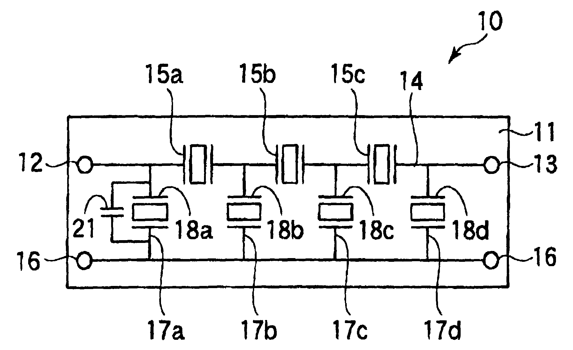
[0100]In FIG. 14, the filter device 10 according to the second embodiment comprises predetermined circuit elements formed on a substrate ...


PUM


Abstract

In a filter device 10 constituted by circuit elements formed on a single substrate 11, the circuit elements includes a first wing section 14 formed between an input signal electrode 12 and an output signal electrode 13, first resonators 15a, 15b, 15c located in the first wiring section 14 and having a predetermined resonance frequency, second wiring sections 17a, 17b, 17c, 17d formed between the first wiring section 14 and a ground electrode 16, second resonators 18a, 18b, 18c, 18d located in the second wiring sections 17a, 17b, 17c, 17d and having an anti-resonance frequency forming a pass-band with the predetermined resonance frequency of the first resonators 15a, 15b, 15c. An effective electric and mechanical coupling factor of the second resonator 18a is different from those of the other resonators 15a, 15b, 15c, 18b, 18c, 18d.

Description

BACKGROUND OF THE INVENTION[0001]The present invention relates to a filter device and a branching filter using the filter device, in particular to a technique effectively applicable to an improvement of sharpness of filter characteristic between pass band and prohibition band in the filter device.[0002]In recent years, a mobile communication terminal equipment, such as a portable telephone and the like has been rapidly developed. Subsequently, it is desired that the mobile communication terminal equipment is small in size, light in weight and capable of saving electric power for the purpose of convenience for portability thereof. In order that the mobile communication terminal equipment may be small in size, light in weight and capable of saving electric power, it is necessary that the filter device used therein is not only small in size and light in weight but also low in insertion loss. Further, from the view point of high speed and large capacity communication, it is also require...

Claims


Application Information

Patent Timeline
IPC IPC(8): H03H9/54H03H9/64H01L41/09H01L41/18H03H9/145H03H9/46H03H9/58H03H9/60
CPCH03H9/6426H03H9/605
Inventor INOUE, KENJISAITOU, HISATOSHI
Owner SNAPTRACK
Why Eureka
Try Eureka