Method of and system for rapidly locating all passive underground electronic marker types

Active Publication Date: 2007-01-30
TEMPO COMM +1
View PDF12 Cites 6 Cited by
  • Summary
  • Abstract
  • Description
  • Claims
  • Application Information

AI Technical Summary

Benefits of technology

[0010]In accordance with another aspect of the present invention, the transmitter may transmit a broadband signal on multiple frequencies. With functionality provided by processing and control hardware and software, for example, it is possible to process the response from markers at multiple frequencies. Such

Problems solved by technology

A common problem associated with conventional utility marker location technologies arises due to the fact that, often, more than one utility type will be in the same vicinity.
The manual switching between marker types introduces the possibility of use

Method used


Image

  • Method of and system for rapidly locating all passive underground electronic marker types
  • Method of and system for rapidly locating all passive underground electronic marker types
  • Method of and system for rapidly locating all passive underground electronic marker types

Examples


second embodiment

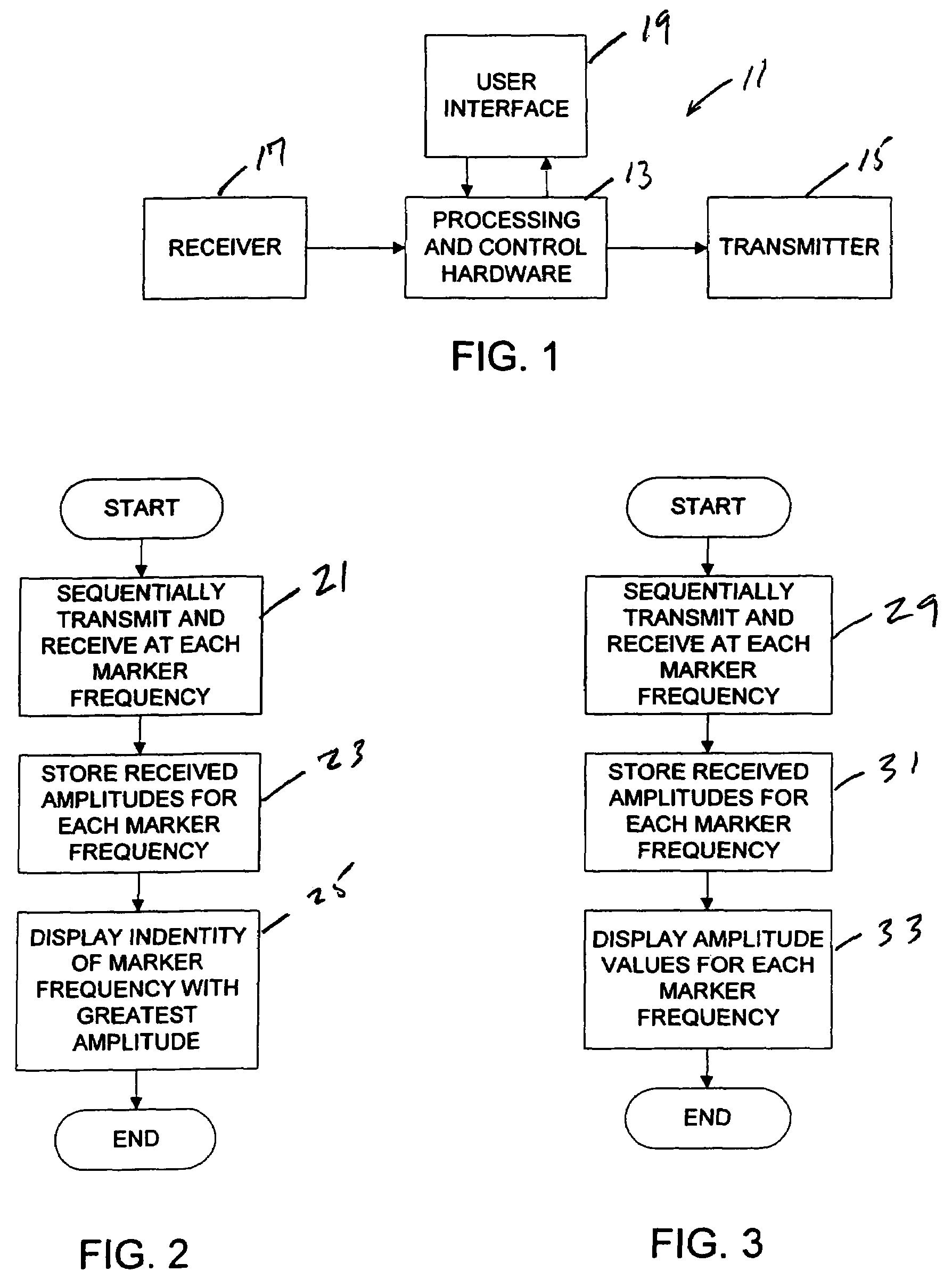
[0027]Referring now to FIG. 3, there is illustrated a flowchart depicting the general operation of a marker location method. FIG. 3 processing is similar to the processing described above with reference to FIG. 2, except that the display operation at block 33 displays an amplitude value for each detected marker frequency. Thus, as indicated at block 29, processing and control hardware may operate transmitter 15 and receiver 17 to transmit and receive, respectively, sequentially at each marker frequency. As indicated at block 31, processing and control hardware 13 may determine and store the amplitude of the return signal received by receiver 17 at each marker frequency. Then, as indicated at block 33, the locator may display the amplitude values for each marker frequency.

[0028]An example of a display according to the FIG. 3 embodiment is illustrated in FIG. 7, in which a display screen is generally indicated at 35. The exemplary display screen 35 displays numerical and graphical ind...

third embodiment

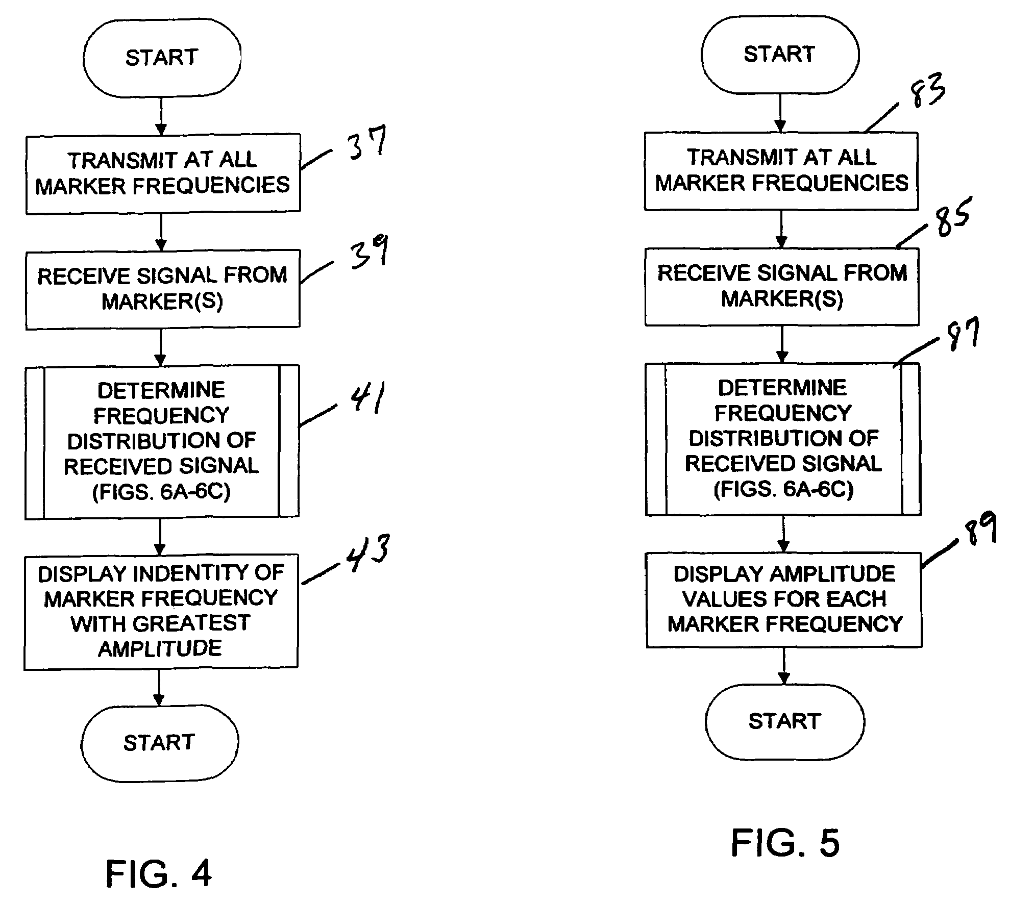
[0029]Referring now to FIG. 4, there is illustrated a flowchart depicting the general operation of a marker location method. As indicated at block 37, transmitter 15 may transmit simultaneously at all marker frequencies. As indicated at block 39, receiver 17 may receive a signal returned from one or more markers. As indicated generally at block 41, processing and control hardware 13 may determine a frequency distribution of the received signal. As set forth below, various frequency distribution determination processes are described in detail with respect to FIGS. 6A–6C. After determining the frequency distribution of the received signal, processing and control hardware 13 may operate the display to display the identity of the marker type with the greatest amplitude, as indicated at block 43. An example of a display according to FIG. 4 processing is illustrated in FIG. 8.

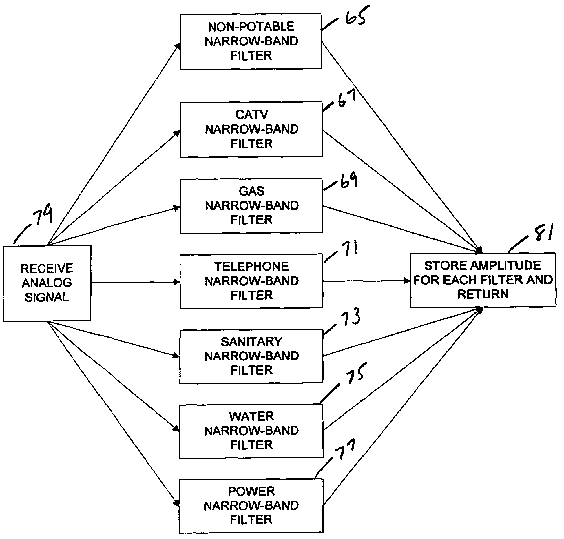
[0030]Referring now to FIG. 6A there is illustrated a synchronous detection process for determining a response fre...

fourth embodiment

[0034]Referring now to FIG. 5, there is illustrated a flowchart depicting the general operation of a marker location method. Operation of the FIG. 5 embodiment is similar to that set forth above with reference to FIG. 4, except that an amplitude value for each marker frequency may be displayed as indicated at block 89. Thus, as indicated at block 83, transmitter 15 may transmit simultaneously at all marker frequencies. As indicated at block 85, receiver 17 may receive a return signal from one or more markers. As indicated generally at block 87, processing and control hardware 13 may determine a frequency distribution of the received signal; as set forth above, various frequency distribution determination processes are described with specific reference to FIGS. 6A–6C. After determining the frequency distribution of the received signal, processing and control hardware 13 may operate the display to display an amplitude value for each marker frequency as indicated at block 89. An exampl...


PUM


Abstract

A method of and system for rapidly locating all passive underground electronic marker types in an area under survey may locate various marker types simultaneously. In accordance with one aspect of the present invention, a marker locator may sequentially transmit and receive multiple frequencies very quickly; alternatively, the transmitter may transmit a broadband signal on multiple frequencies.

Description

CROSS-REFERENCE TO RELATED APPLICATIONS[0001]The present application claims the benefit of U.S. provisional application Ser. No. 60 / 454,504, filed Mar. 12, 2003, entitled “METHOD OF AND SYSTEM FOR RAPIDLY LOCATING ALL PASSIVE UNDERGROUND ELECTRONIC MARKER TYPES,” the disclosure of which is incorporated herein by reference in its entirety.FIELD OF THE INVENTION[0002]Aspects of the present invention relate generally to the field of locating passive underground electronic markers, and more particularly to a method of and system for rapidly locating all passive underground electronic marker types in an area under survey.BACKGROUND OF THE INVENTION[0003]The locations of underground utilities such as power, water, sanitary, telephone, gas, cable television (CATV), and non-potable may be marked with devices known as passive underground electronic markers. Typically, each marker contains one or more Inductor-Capacitor (LC) circuits, or equivalent circuitry, each of which is tuned to a uniqu...

Claims


Application Information

Patent Timeline
IPC IPC(8): G08B13/14G01V15/00H03D3/00H04L27/26H04L27/36
CPCG01V15/00H04L27/364H03D3/009H04L27/2649H04L27/36H03D3/00
Inventor THOMPSON, JAMES W.WOOD, WILLIAM C.
Owner TEMPO COMM
Why Eureka
Try Eureka