Electrophoretic medium and display with improved image stability

a technology of electrophoretic display and image stability, applied in the field of electrophoretic display with improved image stability, can solve the problems of limiting image stability of electrophoretic display, inadequate service life of these displays, and preventing widespread us

Inactive Publication Date: 2007-01-30
E INK CORPORATION
View PDF101 Cites 1057 Cited by
  • Summary
  • Abstract
  • Description
  • Claims
  • Application Information

AI Technical Summary

Problems solved by technology

Nevertheless, problems with the long-term image quality of these displays have prevented their widespread usage.
For example, particles that make up electrophoretic displays tend to settle, resulting in inadequate service-life for these displays.
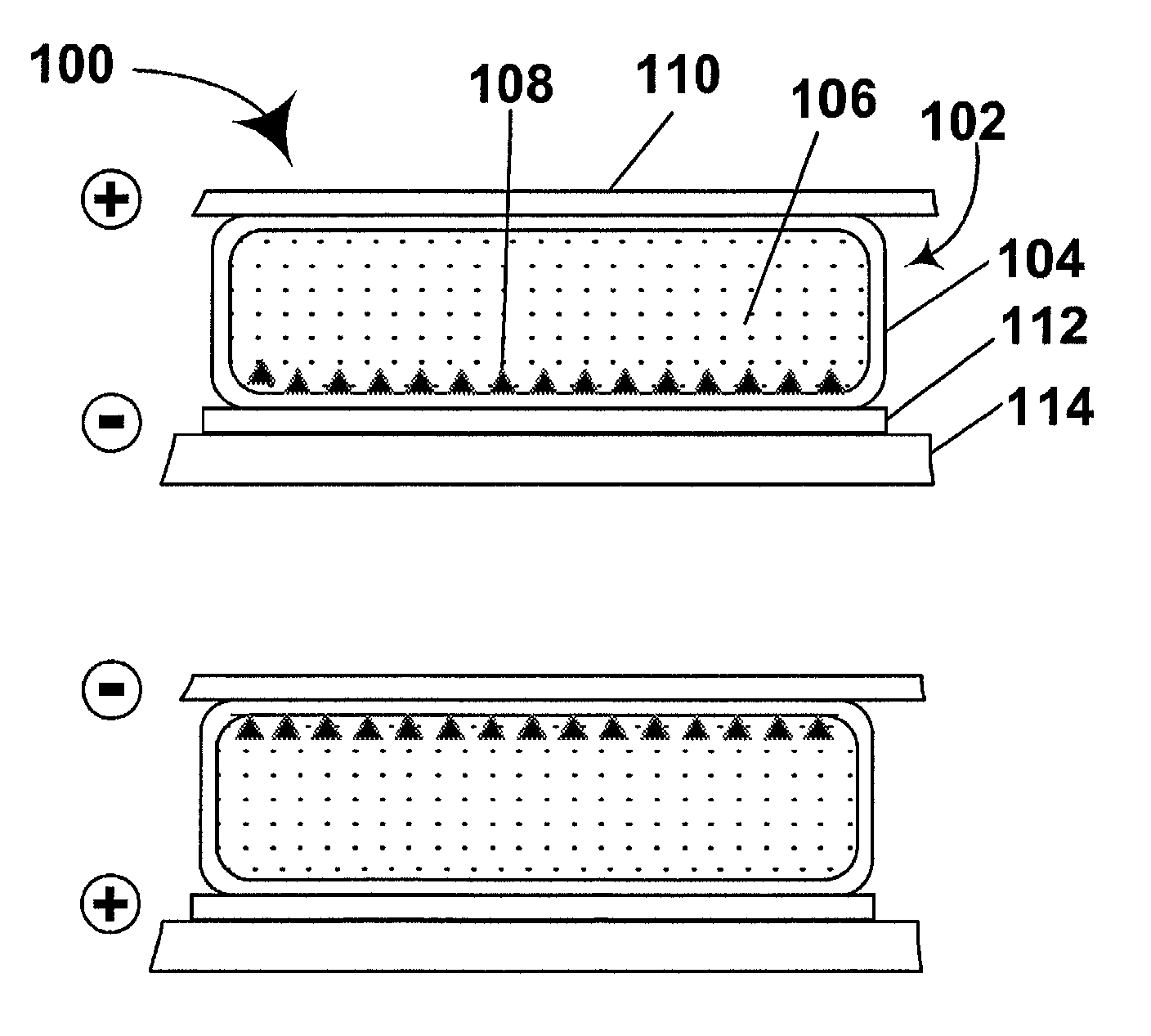
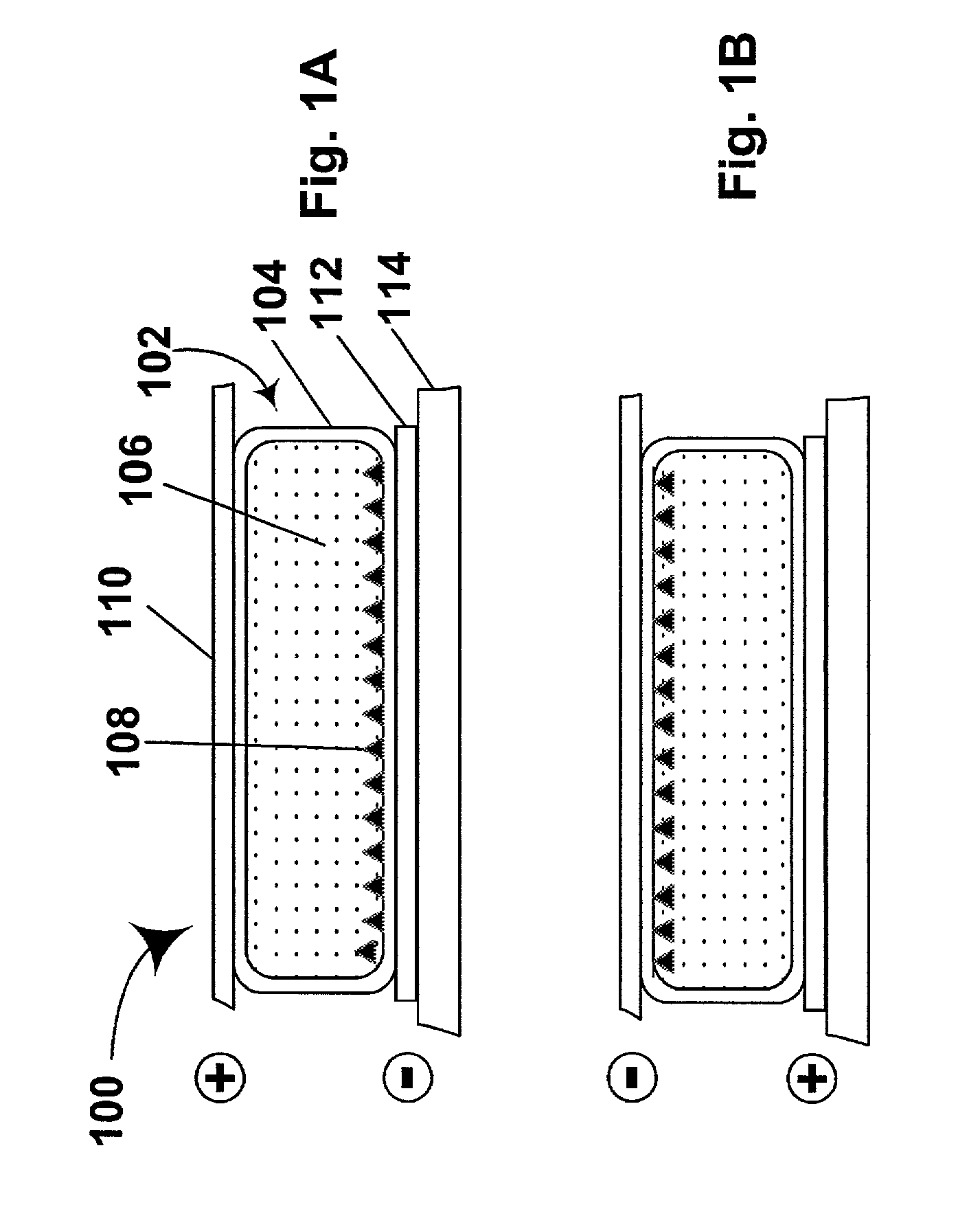
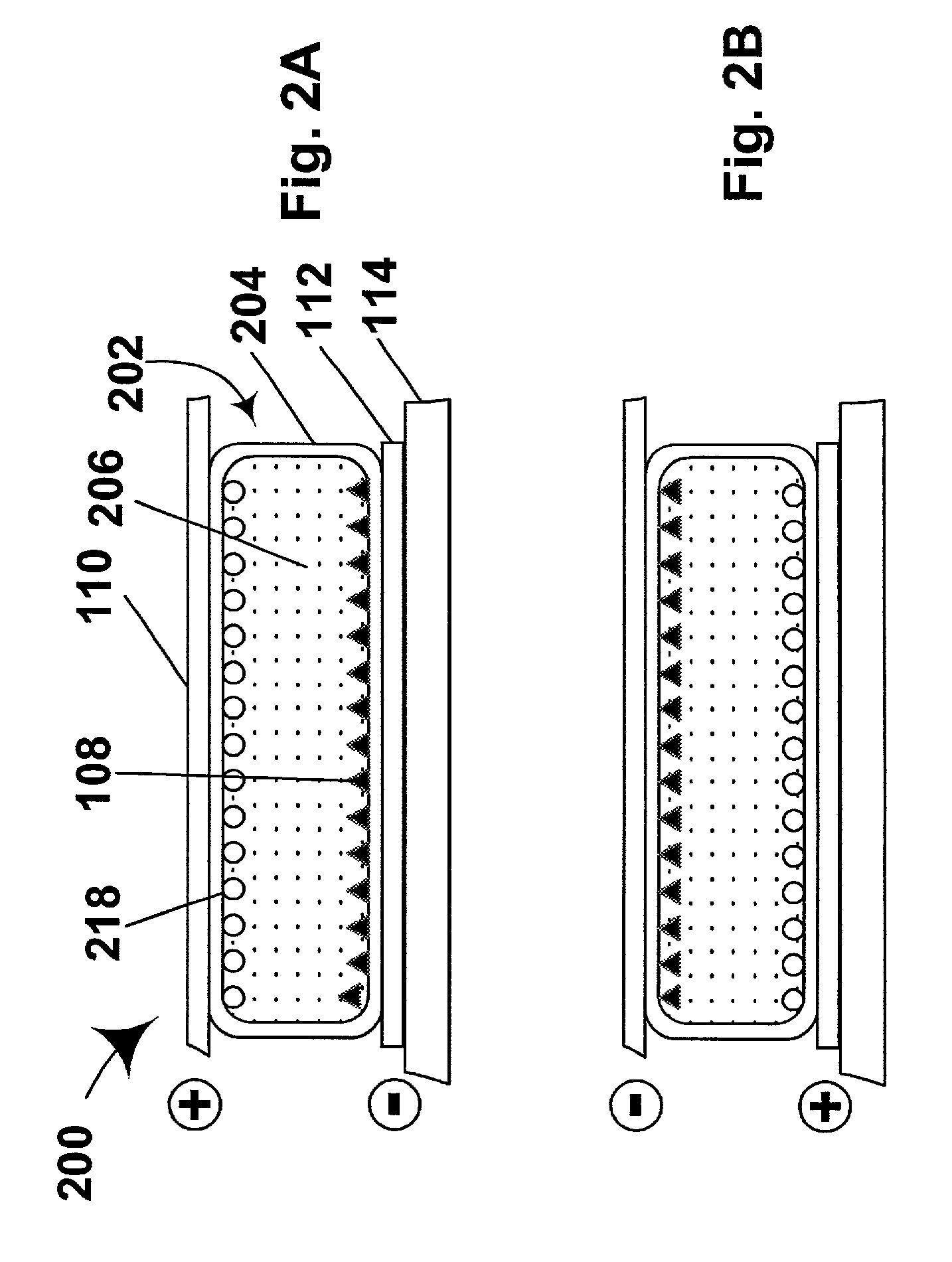
It has been found, by the present inventor and his co-workers, that the main factor limiting image stability in electrophoretic displays of the types described in the aforementioned patents and applications is settling of the electrophoretic pigment particles under gravity.
Unfortunately, as is well known to those skilled in the technology of electrophoretic displays, the electrophoretic mobility of the pigment particles (the rate at which the particles move through the liquid phase under a given electric field) is also inversely proportional to the viscosity of the liquid phase, and thus the switching time of the display (the time required to change a given pixel of the display from one of its optical states to the other essentially the time necessary for the pigment particles to move through the thickness of the liquid medium) is directly proportional to the viscosity of the liquid medium.
Furthermore, especially in the case of small displays such as PDA displays where it may be necessary to move through several “pages” or screens of information to find a desired datum, users will not tolerate switching times substantially in excess of about 1 second.
(Although it is possible to counteract an increase in switching time due to increased viscosity of the suspending fluid by increasing the drive voltage applied to the display, this brings its own set of problems.
Increasing the drive voltage necessarily increases the energy consumption of each driving pulse, and may increase the complexity and cost of the electronic circuitry required to control the driving pulses.
Furthermore, in many battery-driven devices, it is not practicable to increase the driving voltage above certain limits.)
Thus, it has hitherto appeared that the maximum image stability which can be achieved in a PDA or similar electrophoretic display is limited to a value which is substantially lower than is desirable for energy conservation purposes.

Method used


Image

  • Electrophoretic medium and display with improved image stability
  • Electrophoretic medium and display with improved image stability
  • Electrophoretic medium and display with improved image stability

Examples


example 1

[0075]This Example illustrates that the addition of PIB to the suspending fluid in Medium A produces an increase in image stability greater than that attributable to the increase in viscosity caused by the PIB addition.

[0076]A preliminary series of experiments were conducted to determine the effect on the viscosity of the 1:1 w / w Isopar / Halocarbon mixture used in Media A and B. This mixture itself was found to have a viscosity of approximately 0.0021 Pa sec at 25° C., and the addition of the pigments used in Media A and B only slightly increased this viscosity.

[0077]The accompanying FIG. 4 shows the variation of relative viscosity (ηrel), that is, the ratio of the solution viscosity to that of 1:1 w / w Isopar / Halocarbon mixture, with weight fraction of PIB (XPIB) in the solution, this variation being of the expected form; the “best fit” curve is a cubic polynomial fit to the data, except that higher XPIB values not plotted in FIG. 4 were included in the data used to determine the fit...

example 2

[0083]This Example illustrates that the addition of PIB to the suspending fluid in Medium B produces an increase in image stability greater than that attributable to the increase in relative viscosity caused by the PIB addition.

[0084]The PIB and Isopar V addition experiments of Example 1 were repeated with Medium B, except that 15 V switching pulses were used, this being the switching voltage for which Medium B was designed. The results are shown in the accompanying FIG. 6, from which it will be seen that the results achieved with Medium B are qualitatively similar to those achieved with Medium A, as described in Example 1 above, except that the reflectance persistence enhancement provided with PIB only occurs at higher concentrations (greater than about 1.1 percent by weight) with Medium B.

example 3

[0085]This Example illustrates that the images produced using Media A and B with the addition of PIB degrade more slowly than do the images from modified Media A and B having a suspending fluid of essentially the same viscosity but lacking PIB.

[0086]A Medium A display was prepared with 1.47 percent by weight of PIB added to produce a relative viscosity (ηrel, the ratio of the viscosity of the modified medium to the unmodified medium) of 3.90. A similar Medium A display was prepared by using Isopar V to provide a similar relative viscosity (ηrel=3.60). Also, a similar pair of Medium B displays were prepared, one modified with 1.40 percent by weight of PIB (ηrel=3.66) and the other with Isopar V (ηrel=3.60).

[0087]Both pairs of displays were driven to their white state as described in Examples 1 and 2 above, and the L* values of all four displays were monitored over time. The results for the Medium A displays are shown in FIG. 7 and those for the Medium B displays in FIG. 8. In both ca...


PUM

PropertyMeasurementUnit
polydispersity indexaaaaaaaaaa
diametersaaaaaaaaaa
diametersaaaaaaaaaa

Abstract

An electrophoretic medium comprises a plurality of particles suspended in a suspending fluid, the particles being capable of moving through the fluid upon application of an electric field to the medium, the fluid having dissolved or dispersed therein a polymer having a number average molecular weight in excess of about 20,000, the polymer being essentially non-absorbing on the particles. The polymer improves the bistability of the display (i.e., the period for which a written image persist without the display being refreshed) but does not greatly increase the viscosity of the suspending fluid, thus keeping the switching time of the display within reasonable limits. The medium may be encapsulated, or may be in the form a polymer-dispersed electrophoretic medium.

Description

CROSS REFERENCE TO RELATED APPLICATIONS[0001]This application claims priority from Provisional Application Ser. No. 60 / 280,951 filed Apr. 2, 2001. The entire contents of this prior application are herein incorporated by reference.BACKGROUND OF INVENTION[0002]This invention relates to an electrophoretic medium with improved image stability, and to an electrophoretic display including this medium. More specifically, this invention relates to an electrophoretic medium and display which allow improved image stability without unacceptable increases in the switching time or the drive voltage of the display.[0003]Electrophoretic displays have been the subject of intense research and development for a number of years. Such displays can have attributes of good brightness and contrast, wide viewing angles, state bistability, and low power consumption when compared with liquid crystal displays. The terms “bistable” and “bistability” are used herein in their conventional meaning in the art to r...

Claims


Application Information

Patent Timeline
Patent Type & Authority Patents(United States)
IPC IPC(8): G02B26/00G02F1/167G09G3/34
CPCG02F1/167G09G3/344G02F2202/022G09G2320/0252G09G2330/021G09G2320/0233
Inventor WEBBER, RICHARD M.
Owner E INK CORPORATION
Why Eureka
Try Eureka