Device for expelling liquid from a wiping element

a technology of wiping element and liquid, which is applied in the direction of carpet cleaners, drying machines, lighting and heating apparatus, etc., can solve the problem that the known device requires a not inconsiderable energy consumption, and achieves the effect of convenient and convenient washing process and compact construction

Inactive Publication Date: 2007-02-06
ALFRED KARCHER GMBH & CO KG
View PDF10 Cites 8 Cited by
  • Summary
  • Abstract
  • Description
  • Claims
  • Application Information

AI Technical Summary

Benefits of technology

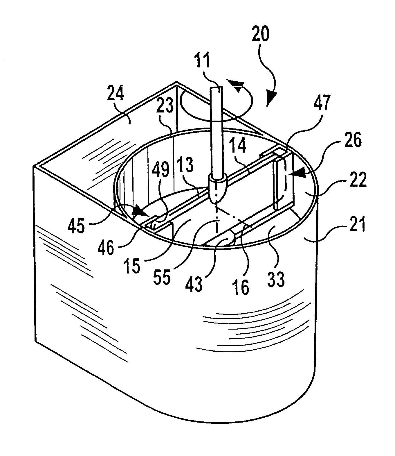
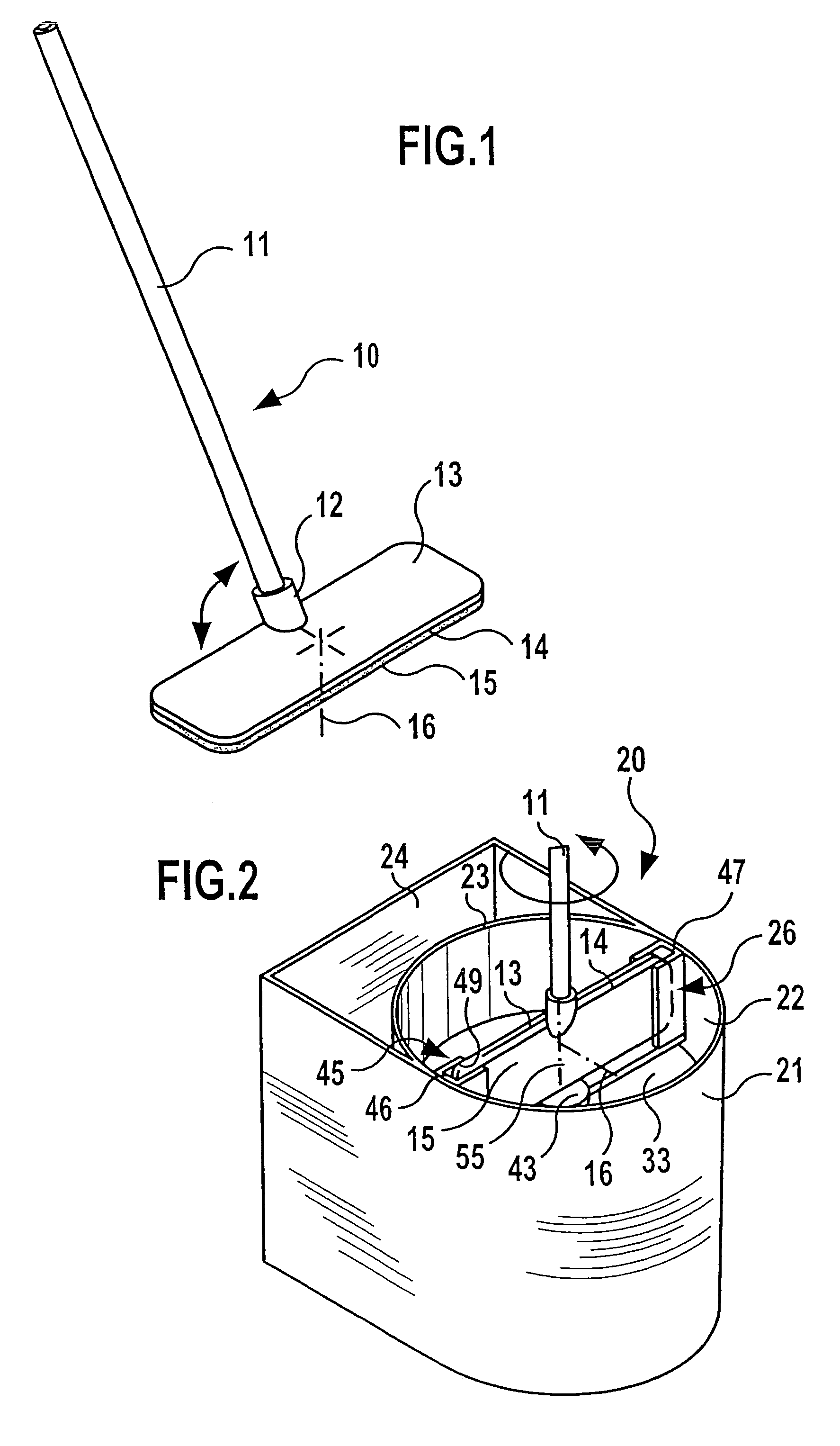
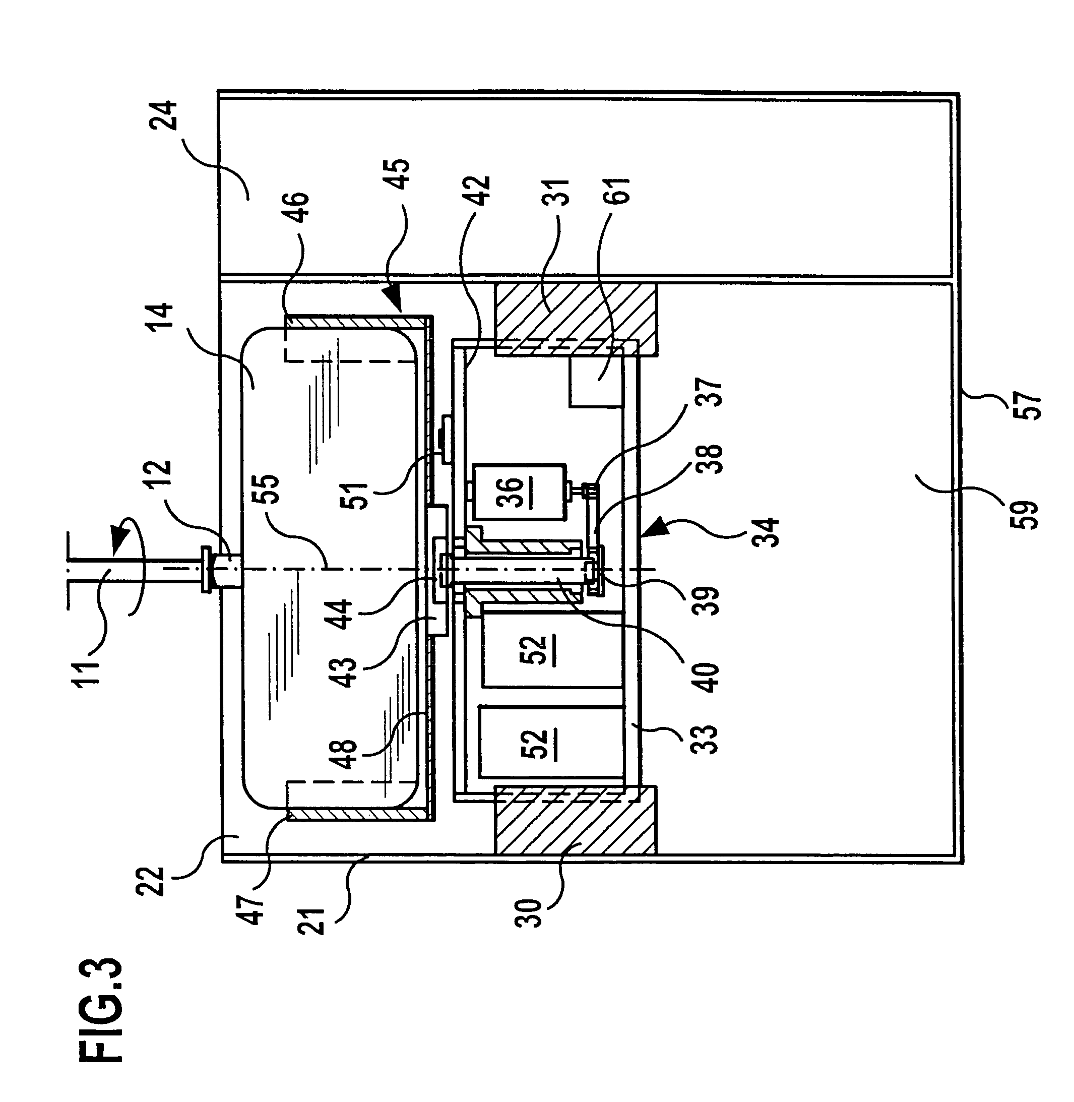
[0008]In accordance with the invention, the wiping element holding device holds the wiping element within the container with a wiping surface aligned at an angle, i.e., inclined or at right angles to the axis of rotation, i.e., the surface normal of the wiping surface is not aligned parallel to the axis of rotation but is at an angle to the axis of rotation. It has been shown that drops of liquid can be expelled from the wiping surface particularly effectively with such an alignment. The inventive device is therefore characterized by a high degree of efficiency. This makes it possible to achieve an effective removal of moisture from the wiping element even with a relatively low rotational speed and, consequently, with a relatively low consumption of energy.
[0029]It is of particular advantage when the container of the expelling device can be closed by means of a container cover. As a result, not only can the risk of a user reaching into the container by mistake during the rotation of the wiping element holding device be reduced but this also offers the possibility of switching the driving device on and off as a function of the position of the container cover in that the container cover interacts with an electric switching element. The container cover can, for example, be articulatedly connected to the container and the switching element can be designed as a push button which switches the driving motor on when the container cover is closed and which switches the drive motor off when the container cover is opened.

Problems solved by technology

The known device does, however, require a not inconsiderable consumption of energy in order to remove moisture from the wiping element reliably.

Method used


Image

  • Device for expelling liquid from a wiping element
  • Device for expelling liquid from a wiping element
  • Device for expelling liquid from a wiping element

Examples


second embodiment

[0052]an inventive expelling device is illustrated in FIG. 4 and designated altogether with the reference numeral 65. This has to a great extent the same construction as the expelling device 20 explained in the above. Therefore, the same reference numerals as in FIGS. 1, 2 and 3 are used for identical components. In this respect, reference is made in full to the preceding explanations.

[0053]The expelling device 65 differs from the expelling device 20 presented in the above with reference to FIGS. 2 and 3 in that a separate washing area 24 for washing the wiping element 14 is omitted. Instead, the expelling device 65 has a spraying device 67 with a spray nozzle 69 secured to the inner side of the wall of the container 21 at the height of the guide parts 46, 47. This spray nozzle is in flow communication with a conveyor pump 71 arranged on the base wall 57 within the compartment 59 for receiving liquid via a hose 70. Liquid may be drawn out of the compartment 59 for receiving liquid a...

fourth embodiment

[0057]In order to remove moisture from the wiping element 87, the handle 81 can be pivoted upwards into a position aligned parallel to the surface normal 89 and, subsequently, the locking mechanism of the hinge 86 which is known per se and not illustrated in the drawings can be released by the user so that the two carrier halves 84 and 85 may be pivoted upwards in the direction towards the handle 81. In accordance with the preceding explanations, the wiping element carrier 83 can then be inserted into a corresponding wiping element holding device of an invention expelling device 95 illustrated in FIG. 7 with carrier halves 84 and 85 pointing upwards at an angle and surface normals 89 of the wiping element 87 aligned accordingly at an angle to the axis of rotation 55. The expelling device 95 is to a great extent identical to the expelling device 65 explained in the above with reference to FIG. 4. It is, therefore, illustrated in FIG. 7 in an extremely simplified manner. It differs fr...


PUM

PropertyMeasurementUnit
rotationaaaaaaaaaa
angleaaaaaaaaaa
anglesaaaaaaaaaa

Abstract

The invention relates to a device for expelling liquid from a wiping element which is held on a wiping head of a surface cleaning device so as to form a wiping surface, comprising a container, in which a wiping element holding device accommodating the wiping element as well as a driving device are arranged, wherein the wiping element holding device can be driven by means of the driving device so as to rotate about an axis of rotation. In order to further develop the device in such a manner that it has a lower consumption of energy it is suggested in accordance with the invention that the wiping element holding device form a receiving means, into which the wiping element can be inserted with a surface normal of the wiping surface aligned at an angle to the axis of rotation.

Description

[0001]This application is a continuation of International Application No. PCT / EP03 / 04775 filed on May 7, 2003.[0002]The present disclosure relates to the subject matter disclosed in International application No. PCT / EP03 / 04775 of May 7, 2003, which is incorporated herein by reference in its entirety and for all purposes.BACKGROUND OF THE INVENTION[0003]The invention relates to a device for expelling liquid from a wiping element which is held on a wiping head of a surface cleaning device so as to form a wiping surface, comprising a container, in which a wiping element holding device accommodating the wiping element as well as a driving device are arranged, wherein the wiping element holding device can be driven by means of the driving device so as to rotate about an axis of rotation.[0004]For the purpose of cleaning a soiled surface, in particular, a floor surface, a wiping element, for example, a wiping pad or a wiper covering is often used which is held on a wiping head so as to fo...

Claims


Application Information

Patent Timeline
Patent Type & Authority Patents(United States)
IPC IPC(8): A47L13/58
CPCA47L13/58
Inventor RUST, HENDRIKDEMIRTAS, YUNUSSCHWARZ, RONALD
Owner ALFRED KARCHER GMBH & CO KG
Why Eureka
Try Eureka