Spin beam

Inactive Publication Date: 2007-02-06
SAURER GMBH & CO KG
View PDF28 Cites 8 Cited by
  • Summary
  • Abstract
  • Description
  • Claims
  • Application Information

AI Technical Summary

Benefits of technology

[0009]In the case of a spin beam heated by a heat transfer medium, it is usually not possible with this heating principle to achieve the pyrolysis temperature required for the regeneration process. For this reason separate regeneration heating is provided for the regeneration process in the form of electrical resistance heating, a hot air blower, or the like.
[0010]To carry out the regeneration process, the regeneration heating is able to heat the melt-conducting components to temperatures above the operating temperature. This temperature is preferably in the range of 450 to 550° C., which thermally destroys the organic deposits.
[0011]If the spin beam is heated by an electrical heating unit, the unit can simultaneously be put to practical use as regeneration heating, and is capable of heating the spin beam to the regeneration temperature.
[0012]The thermal destruction of the organic deposits generates gases and vapors in the spin beam. For this reason, in one preferred refinement of the invention means are provided for exhausting the generated gases and vapors. In one particularly preferred refinement the exhausted gases and vapors are filtered.
[0013]For the case in which the spin beam is heated using a heat transfer medium, in one advantageous refinement of the invention means are provided to drain off the heat transfer medium for the duration of the regeneration process, and to store it outside the spin beam which is heated to regeneration temperature. In one particularly advantageous refinement of the invention, means are provided to remove the vapors produced by evaporation of the heat transfer medium during the regeneration process.
[0014]One exemplary embodiment is described in greater detail below, with reference to the accompanying drawings.

Problems solved by technology

In the case of a spin beam heated by a heat transfer medium, it is usually not possible with this heating principle to achieve the pyrolysis temperature required for the regeneration process.

Method used


Image

  • Spin beam
  • Spin beam
  • Spin beam

Examples


Embodiment Construction

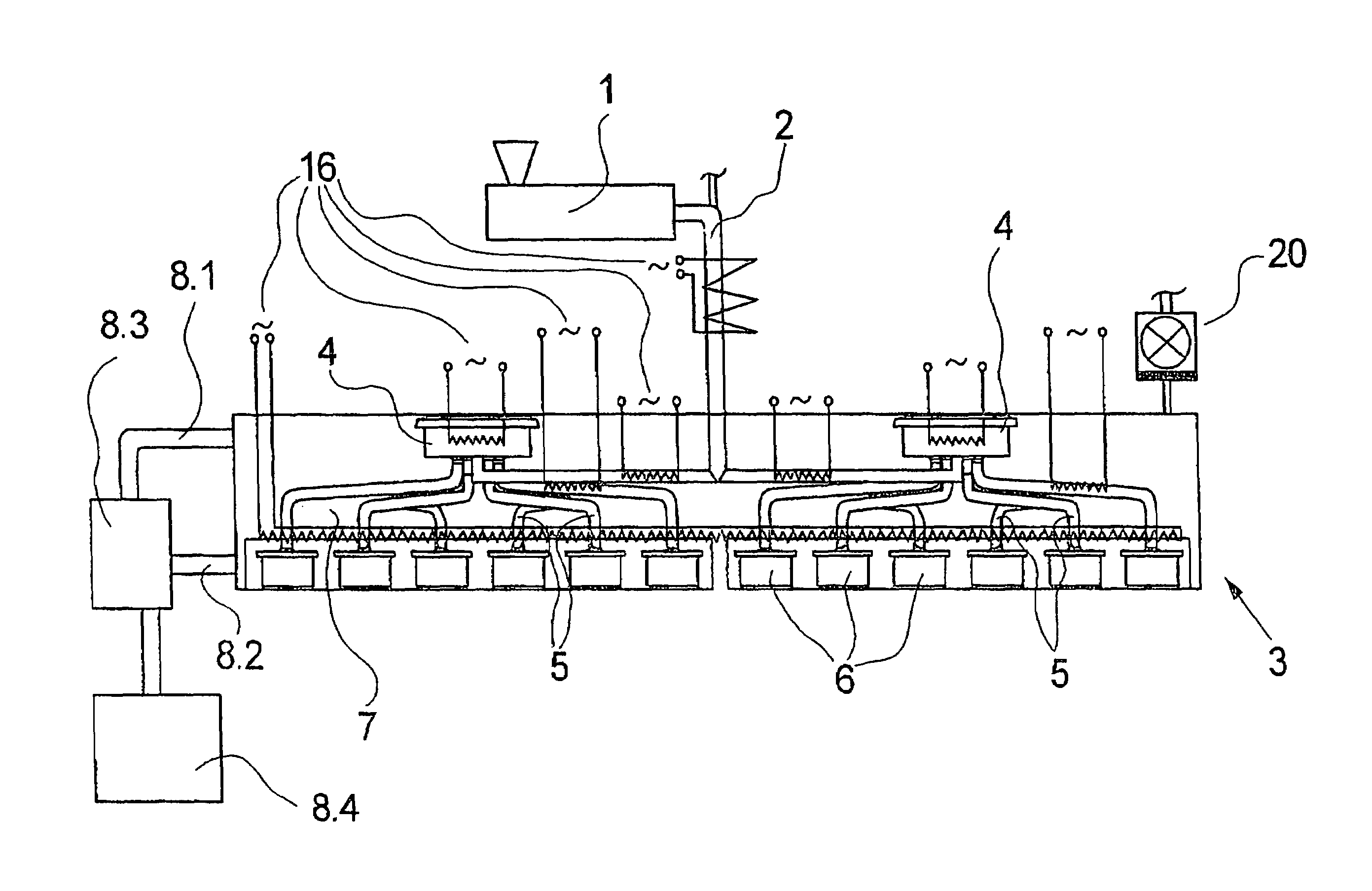
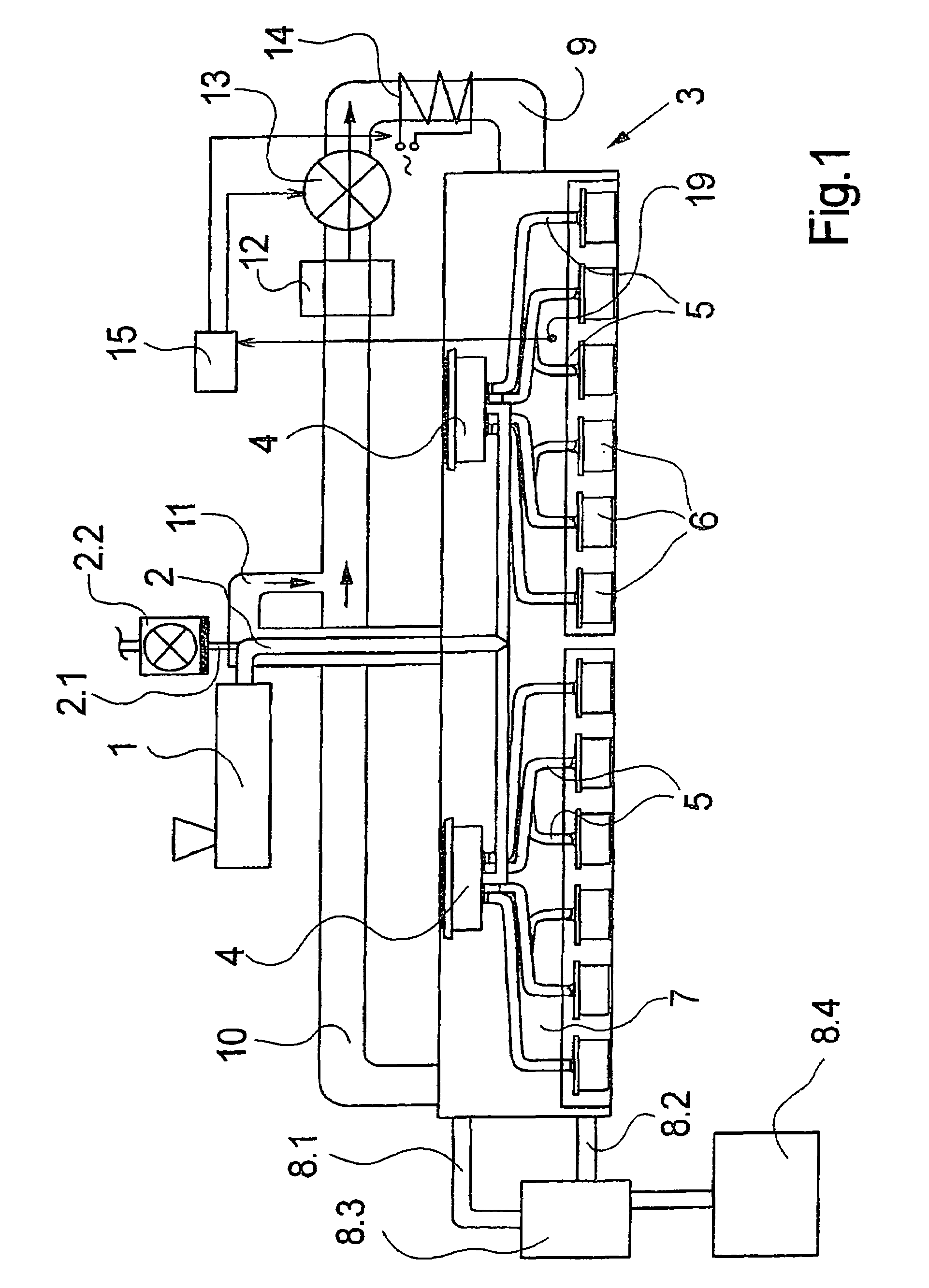
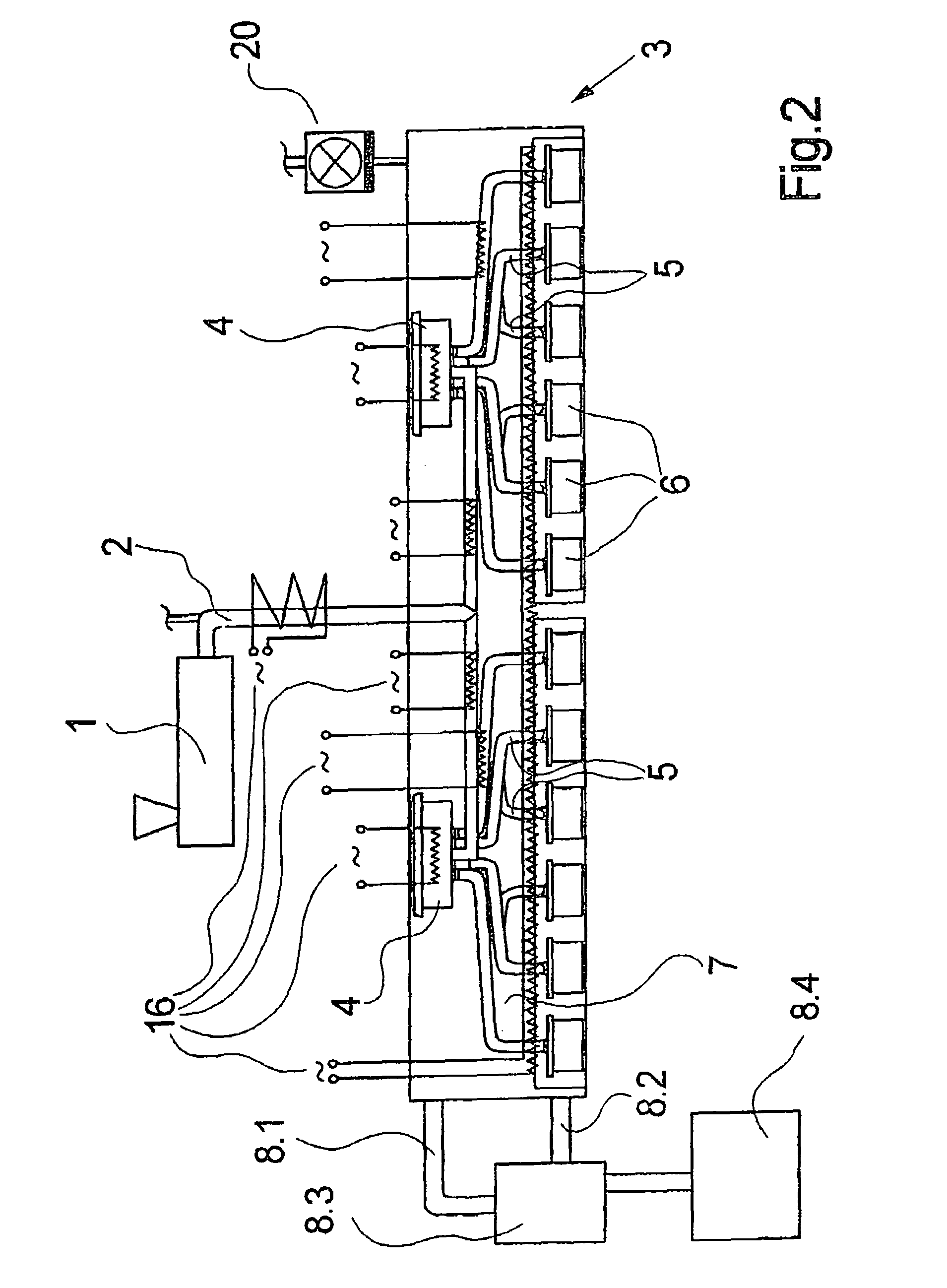
[0018]FIG. 1 illustrates in sectional view an inventive apparatus for spinning. A polymer melt is fed from an extruder 1 via a melt feed line 2 to spin beam 3. Instead of extruder 1, a direct polycondensation reactor may be used here as the source for the polymer melt. Inside spin beam 3, melt feed line 2 is apportioned to two spinning pumps 4. Spinning pumps 4 distribute the polymer melt, metered via distribution lines 5, to the individual spinning cans, not shown, which are accommodated in spinning can receivers 6. The filaments for forming the thread are extruded from the polymer melt in these spinning cans. The number of spinning can receivers 6 as well as the number of spinning pumps 4 are chosen here by way of example.

[0019]Inside spin beam 3, a cavity 7 is formed so that it may be filled with a heat transfer medium. This heat transfer medium circulates through an operational heating means 8.3 via an inlet 8.1 and an outlet 8.2. Spin beam 3 is thus heated to operating temperat...


PUM

PropertyMeasurementUnit
temperatureaaaaaaaaaa
temperaturesaaaaaaaaaa

Abstract

An apparatus for spinning melt-spun filament yarns including a spin beam is disclosed. A polymer melt fed to a spin beam is distributed within the spin beam to a plurality of spinning cans mounted on the spin beam. To reduce costs to the manufacturer for ensuring ease of disassembly of the spin beam, as well as to avoid the need for disassembling the spin beam and having a furnace on hand, the spin beam is provided with an integrated or removably attachable regenerative heater by which the melt-conducting components of the spin beam can be heated to a regeneration temperature of between about 450 to 550° C. to pyrolytically remove the deposits.

Description

BACKGROUND OF INVENTION[0001]Apparatuses used for melt spinning of synthetic threads are known from German Patent Application 195 40 907 A1, for example.[0002]To this end, a polymer melt is fed to a spin beam from a melt source, for example an extruder or a polymerization unit. Inside the spin beam the melt is fed to usually one, or, by use of a distributor, multiple, metering pumps, which distribute the melt at a defined volumetric flow rate to spin cans in which the filaments are formed. The elements of the spin beam, that is, the distributor, metering pumps, piping, and spin cans, are all heated together and are enclosed by insulation.[0003]Occasionally the physical characteristics of the polymers used for the melt spinning are altered under the influence of temperature and time. Polyamide 6.6, for example, tends to undergo post-polycondensation, resulting in an unmeltable hardening of the material and thus to deposits, or, in extreme cases, to plugging, in the lines. For this re...

Claims


Application Information

Patent Timeline
Patent Type & Authority Patents(United States)
IPC IPC(8): D01D5/084D01D1/09
CPCD01D1/09
Inventor REUTTER, TILMAN
Owner SAURER GMBH & CO KG
Why Eureka
Try Eureka