
Inductive proximity sensor using coil time constant for temperature compensation

a technology of time constant and proximity sensor, which is applied in the direction of magnetic variables, pulse techniques, instruments, etc., can solve the problems of coil inductance and complex conventional circuits, and achieve the effects of facilitating accurate ascertaining, reducing temperature drift effects, and facilitating increased accuracy of proximity sensors

Active Publication Date: 2007-02-06
ROCKWELL AUTOMATION TECH
View PDF6 Cites 66 Cited by
  • Summary
  • Abstract
  • Description
  • Claims
  • Application Information

AI Technical Summary

Benefits of technology

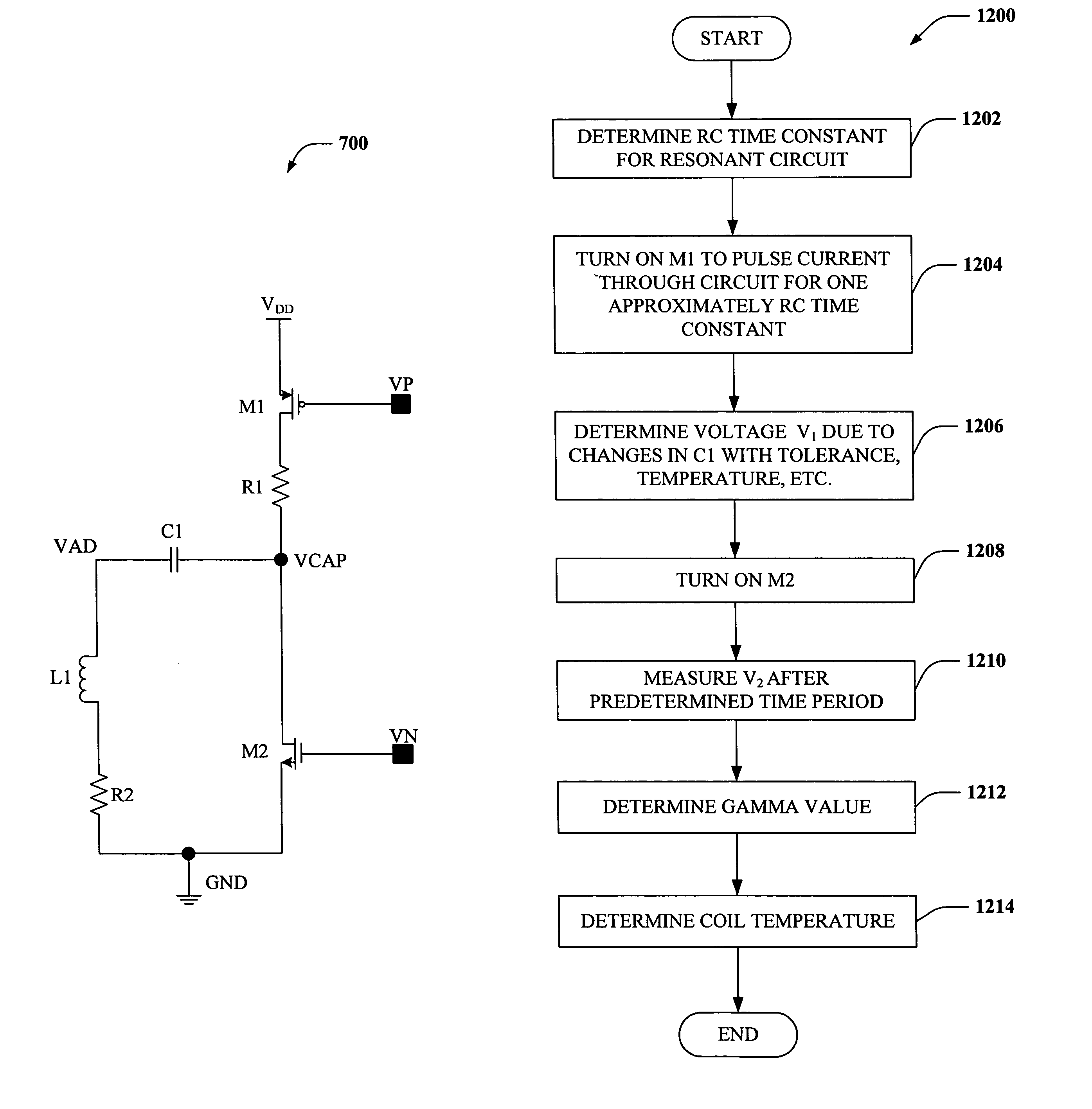
[0008]The subject invention provides for systems and methods that facilitate increased accuracy in proximity sensors via determining a time constant value associated with a damping resonant circuit in a proximity sensor. This determination mitigates temperature drift effects and facilitates accurately ascertaining when a target has been sensed despite temperature deviations in a sensing coil. More specifically, the present invention can ascertain coil temperature via determining a value, γ, associated with an L / R time constant for a sensing coil, where L is inductance and R is resistance, associated with the resonant circuit. Thus, the invention can account for an effect of temperature on coil inductance to more accurately detect coil temperature.

Problems solved by technology

Such conventional circuits are complex and require filters to separate DC and AC energy.
However, coil inductance is affected by the introduction of a target into the sensing field, even at extended ranges.

Method used


Image

  • Inductive proximity sensor using coil time constant for temperature compensation
  • Inductive proximity sensor using coil time constant for temperature compensation
  • Inductive proximity sensor using coil time constant for temperature compensation

Examples


Embodiment Construction

[0026]The present invention will now be described with reference to the drawings, wherein like reference numerals are used to refer to like elements throughout. The present invention will be described with reference to systems and methods for determining coil temperature in a proximity sensor via measuring a time constant of the coil. It should be understood that the description of these exemplary aspects are merely illustrative and that they should not be taken in a limiting sense.

[0027]The term “component” can refer to a computer-related entity, either hardware, a combination of hardware and software, software, or software in execution. For example, a component can be a process running on a processor, a processor, an object, an executable, a thread of execution, a program and a computer. By way of illustration, both an application running on a server and the server can be components. A component can reside in one physical location (e.g., in one computer) and / or can be distributed ...


PUM


Abstract

Systems and methods are disclosed that facilitate determining coil temperature in a proximity sensor, such as an extended range inductive proximity sensor. Voltage measurements can be taken before, and during, damped oscillatory decay of a voltage in a resonant circuit in the proximity sensor to determine a value, γ, associated with an inductive time constant for the resonant circuit. The gamma value comprises information related to both inductance and resistance in the sensor coil, and can be employed to determine coil temperature. Derivation of the gamma value, and thus of coil temperature, can utilize a current pulse of a duration of approximately one RC time constant of the resonant circuit, thus mitigating current consumption by the proximity sensor during temperature assessment.

Description

TECHNICAL FIELD[0001]The present invention relates generally to industrial control systems, and more particularly to systems and methodologies that facilitate reduction of current consumption in industrial control devices and temperature compensation, such as proximity sensors.BACKGROUND OF THE INVENTION[0002]Industrial control systems have enabled modern factories to become partially or completely automated in many circumstances. These systems generally include a plurality of Input and Output (I / O) modules that interface at a device level to switches, contactors, relays and solenoids along with analog control to provide more complex functions such as Proportional, Integral and Derivative (PID) control. Communications have also been integrated within the systems, whereby many industrial controllers can communicate via network technologies such as Ethernet, Control Net, Device Net or other network protocols and also communicate to higher level computing systems. Generally, industrial...

Claims


Application Information

Patent Timeline
IPC IPC(8): G01B7/00G01R33/025
CPCH03K17/9547H03K17/9502
Inventor POND, ROBERT J
Owner ROCKWELL AUTOMATION TECH
Learn More