Portable antenna positioner apparatus and method

a positioner and portable technology, applied in the direction of pivotable antennas, antenna details, antennas, etc., can solve the problems of small motors used in geosynchronous applications, and achieve the effects of convenient hand or shipment, low cost, and simple or automated setup

Active Publication Date: 2007-02-06
AQYR TECH INC
View PDF3 Cites 33 Cited by
  • Summary
  • Abstract
  • Description
  • Claims
  • Application Information

AI Technical Summary

Benefits of technology

[0008]Embodiments of the invention provide a lightweight, collapsible and rugged antenna positioner for use in receiving low earth orbit and geosynchronous satellite transmissions. By collapsing the antenna positioner, it may be readily carried by hand or shipped in a compact container. For example, embodiments of the invention may be stored in a common carry-on bag for an airplane. The antenna positioner may be used in remote locations with simple or automated setup and orientation. Embodiments of the invention may be produced at low cost for disposable applications. The apparatus can be scaled to any size by altering the size of the various components. The gain requirements for receiving any associated satellite transmission may be altered by utilizing more sophisticated and efficient antennas as the overall size of the system is reduced.
[0009]The movement of an antenna coupled with embodiments of the portable antenna positioner allows for low earth orbit, geostationary or geosynchronous location and tracking of a desired satellite. Since the slew rate requirements are small for geosynchronous satellites, the motors used in geosynchronous applications may be small.
[0010]One embodiment of the invention may be used, for example, after extending stabilizer legs and an adjustable leg to provide a stable base upon which to operate. With a battery already in the apparatus, pinch paddles are squeezed in order to extend the antenna mounting plate to the full range of one positioning arm arrangement. Next, the second positioning arm is locked via a release knob. A motor release knob is engaged and after a PC is connected to the apparatus, the apparatus is ready to acquire a satellite. The entire setup process can occur in rapid fashion. Another embodiment of the invention may utilize alternate mechanical positioning devices such as an arm that extends upward and allows for azimuth and elevation motors to adjust the antenna positioning. Another embodiment of the invention utilizes a smaller azimuth motor and limited range in order to lower the overall weight of the apparatus.
[0011]One or more embodiments utilize an adjustable leg or legs that may be motorized with for example a stepper motor. These embodiments are able to alter the effective azimuth angle of a satellite relative to the apparatus so that the satellite is far enough away from the zenith to prevent “keyholing”.
[0019]In addition, one or more embodiments of the invention may comprise mass storage devices including hard drives or flash drives in order to record programs or channels at particular times. The apparatus may also comprise the ability to transmit data, and transmit at preset times. Use of solar chargers or multiple input cables allows for multiple batteries or the switching of batteries to take place. The apparatus may search for satellites in any band and create a map of satellites found in order to determine or improve the calculated pointing direction to a desired satellite. The apparatus may also comprise stackable modules that allow for cryptographic, routing, power supplies or additional batteries to be added to the system. Such modules may comprise a common interface on the top or bottom of them so that one or more module may be stacked one on top of another to provide additional functionality. For lightweight deployments all external stackable modules including the legs may be removed depending on the mission requirements.

Problems solved by technology

Since the slew rate requirements are small for geosynchronous satellites, the motors used in geosynchronous applications may be small.

Method used


Image

  • Portable antenna positioner apparatus and method
  • Portable antenna positioner apparatus and method
  • Portable antenna positioner apparatus and method

Examples


Embodiment Construction

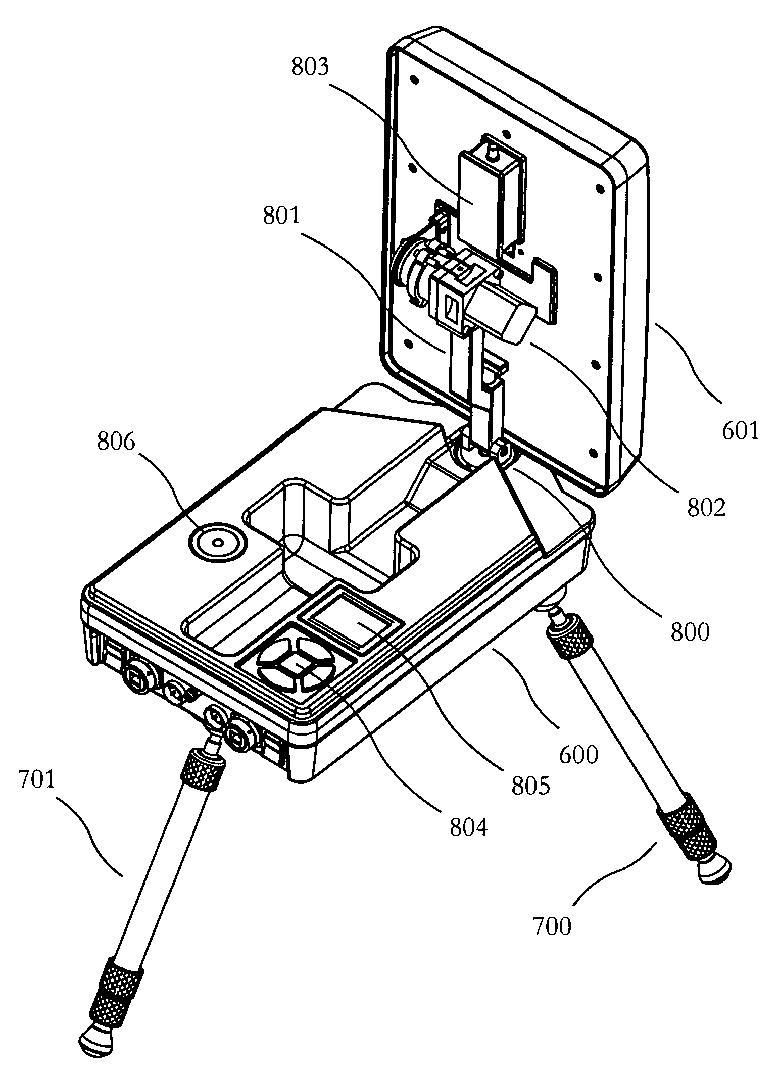
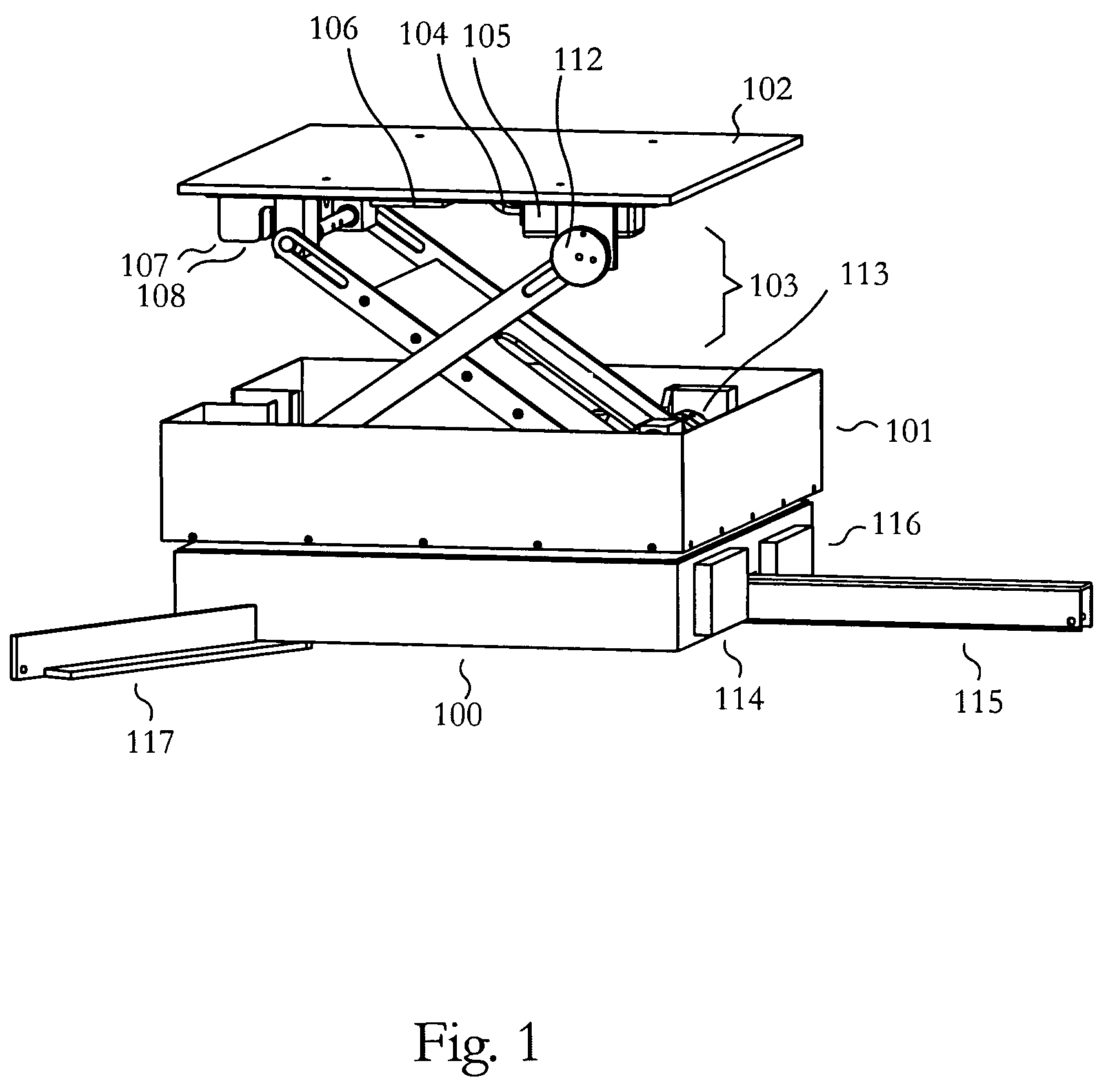
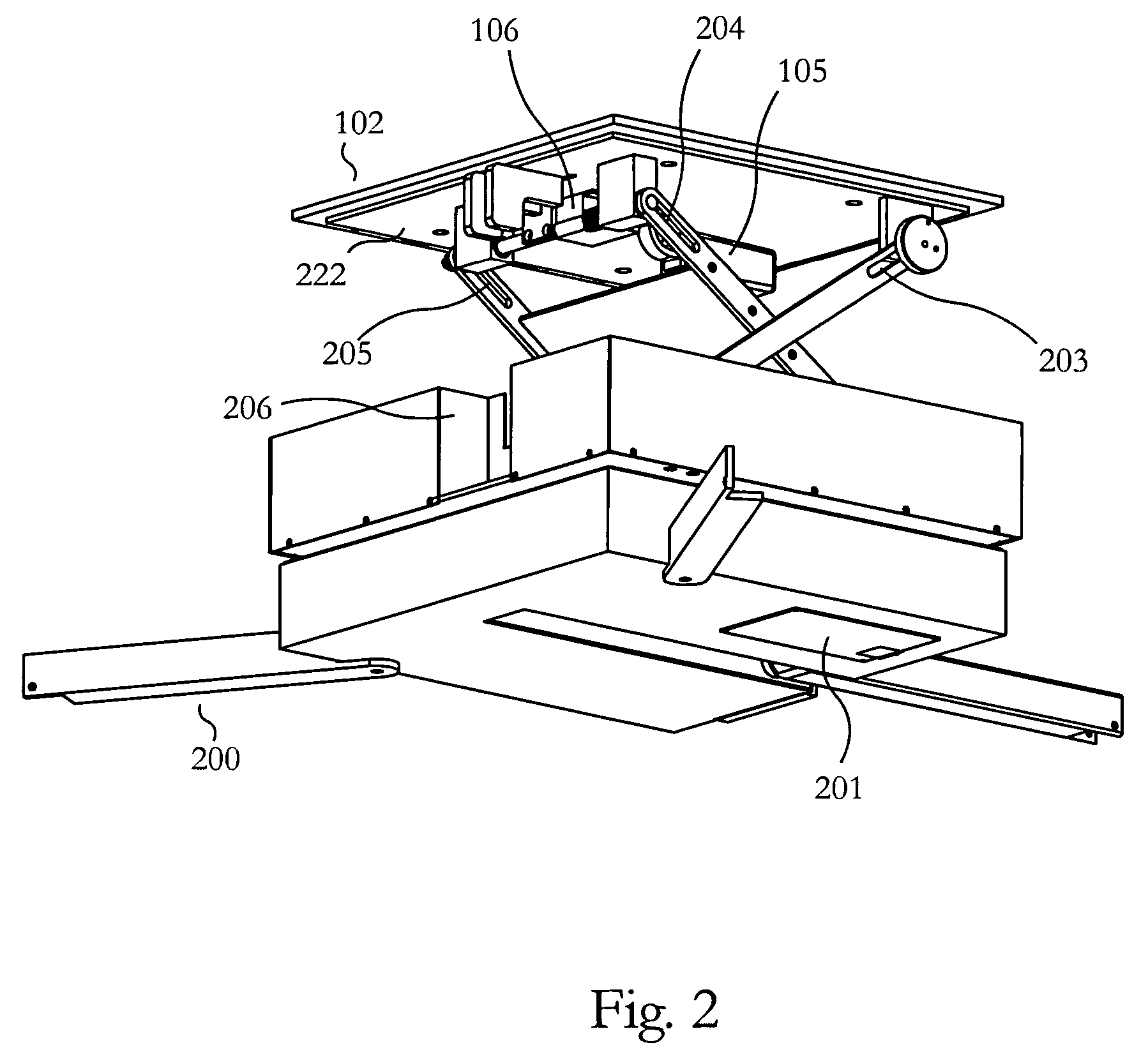
[0031]Embodiments of the invention provide a self contained lightweight, collapsible and rugged antenna positioner for use in receiving and transmitting to low earth orbit, geosynchronous and geostationary satellites. In the following exemplary description numerous specific details are set forth in order to provide a more thorough understanding of embodiments of the invention. It will be apparent, however, to an artisan of ordinary skill that the present invention may be practiced without incorporating all aspects of the specific details described herein. Any mathematical references made herein are approximations that can in some instances be varied to any degree that enables the invention to accomplish the function for which it is designed. In other instances, specific features, quantities, or measurements well-known to those of ordinary skill in the art have not been described in detail so as not to obscure the invention. Readers should note that although examples of the invention...


PUM


Abstract

Embodiments of the portable antenna positioner described provide a lightweight, collapsible and rugged antenna positioner for use in receiving low earth orbit, geostationary and geosynchronous satellite transmissions. By collapsing the antenna positioner, it may be readily carried by one person or shipped in a compact container. The antenna positioner may be used in remote locations with simple or automated setup and orientation. In order to operate the apparatus, azimuth is adjusted by rotating an antenna in relation to a positioner base and elevation is adjusted by rotating an elevation motor coupled with the antenna. The apparatus may update ephemeris data via satellite, may comprise a built-in receiver and may couple with a second positioner base comprising cryptographic, router or power functionality. The apparatus may comprise storage devices such as a hard drive or flash disk for storing data to and from at least one satellite.

Description

[0001]This application takes priority from U.S. Provisional Patent Application to Webb et al., entitled “Portable Antenna Positioner Apparatus and Method”, Ser. No. 60 / 521,436 filed Apr. 26, 2004, which is hereby incorporated herein by reference.[0002]This invention was made with Government support under F19628-03-C-0039 awarded by US Air Force, Department of Defense. The Government has certain rights in the invention.BACKGROUND OF THE INVENTION[0003]1. Field of the Invention[0004]Embodiments of the invention described herein pertain to the field of antenna positioning systems. More particularly, but not by way of limitation, these embodiments enable the positioning of antennas by way of a compact, lightweight, portable, self-aligning antenna positioner that is easily moved by a single user and allows for rapid setup and alignment.[0005]2. Description of the Related Art[0006]An antenna positioner is an apparatus that allows for an antenna to be pointed in a desired direction, such a...

Claims


Application Information

Patent Timeline
Patent Type & Authority Patents(United States)
IPC IPC(8): H01Q3/00H01Q1/08H01Q1/12
CPCH01Q1/08H01Q1/084H01Q1/1235H01Q3/08H01Q1/42H01Q3/005H01Q1/125
Inventor WEBB, SPENCERMARTIN, DAVID
Owner AQYR TECH INC
Why Eureka
Try Eureka