Control of distributed printing using data output control module

a control module and data output technology, applied in the direction of digital output to print units, instruments, digital computers, etc., can solve the problem of shortening the total time required for printing, and achieve the effect of good operation and favorable resulting prints

Inactive Publication Date: 2007-02-06
SEIKO EPSON CORP
View PDF33 Cites 31 Cited by
  • Summary
  • Abstract
  • Description
  • Claims
  • Application Information

AI Technical Summary

Benefits of technology

[0012]The object of the present invention is thus to solve at least part of the above problems and to ensure favorable resulting prints with good operatability.

Problems solved by technology

Compared with the prior art technique, this technique effectively shortens the total time required for printing.

Method used


Image

  • Control of distributed printing using data output control module
  • Control of distributed printing using data output control module
  • Control of distributed printing using data output control module

Examples


first embodiment

A. First Embodiment

[0107]A1. General Hardware Structure

[0108]A2. Distributed Printing Process

[0109]A3. Virtual Printer Driver

[0110]A4. User Interface

[0111]A5. Computer Programs

[0112]A6. Effects of Embodiment

B. Second Embodiment

[0113]B1. User Interface

[0114]B2. Computer Programs

[0115]B3. Effects of Embodiment

C. Third Embodiment

[0116]C1. Distributed Printing Process

[0117]C2. Computer Programs

[0118]C3. Effects of Embodiment

A1. General Hardware Structure

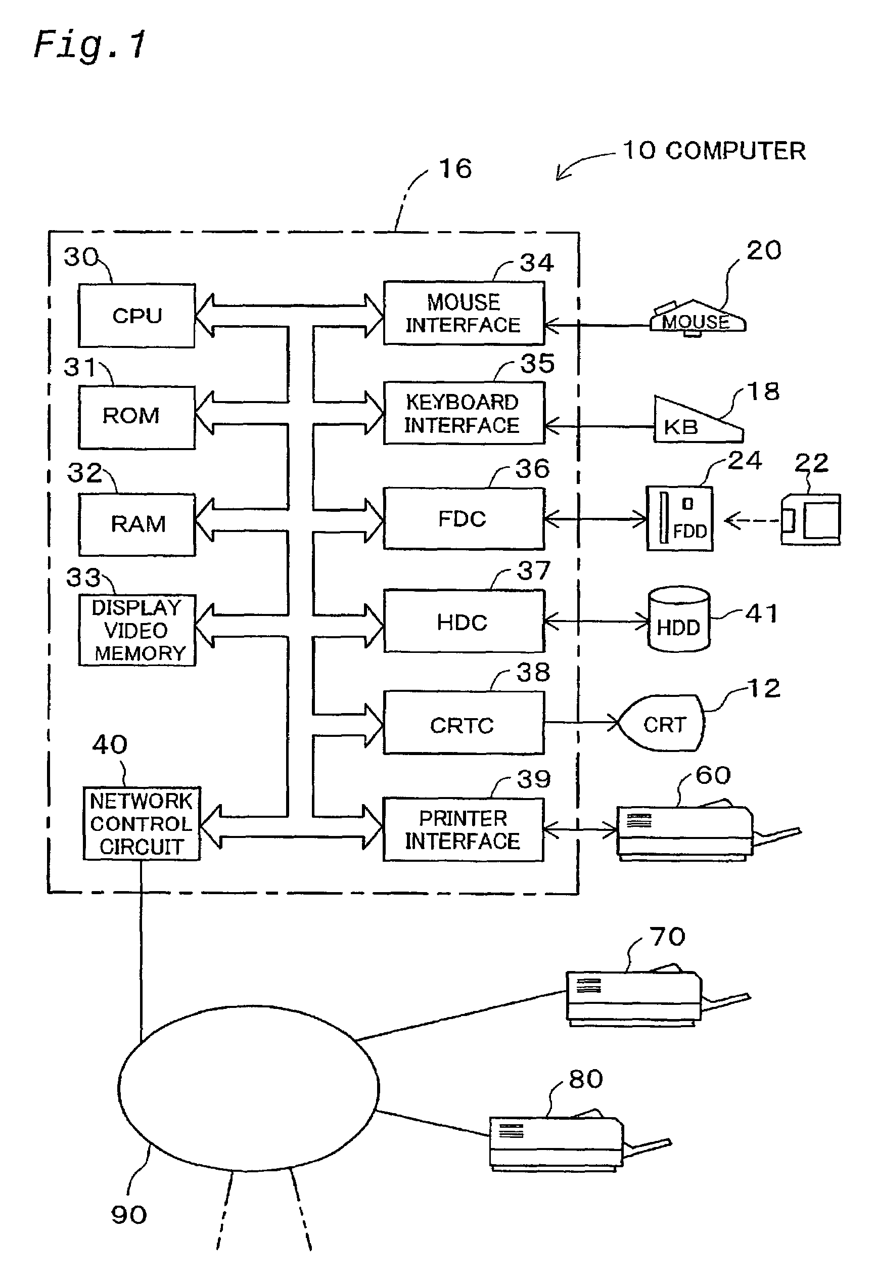
[0119]FIG. 1 is a block diagram schematically illustrating the hardware structure of a computer system in a first embodiment of the present invention. As illustrated, the computer system of the first embodiment includes a computer 10, which is connected with a plurality of printers 70, 80, . . . having substantial computer functions via a computer network 90 constructed as a Local Area Network (LAN). The computer network 90 is, however, not restricted to the LAN but may be any of diverse networks like the Internet, an Intranet, and a Wid...

second embodiment

B. Second Embodiment

B1. User Interface

[0214]The following describes a second embodiment of the present invention. The details of ‘A1. General Hardware Structure’, ‘A2. Distributed Printing Process’, and ‘A3. Virtual Printer Driver’ discussed in the first embodiment are adopted in the second embodiment of the present invention. The same parts as those of the first embodiment are expressed by the same numerals. The differences between the first embodiment and the second embodiment are part of the details of the user interface and part of the computer programs. The details of the user interface are discussed first.

[0215]Like the first embodiment, in the structure of the second embodiment, a dialog box ‘Distributed Printing Properties’ is provided as the user interface. FIG. 21 illustrates a dialog box WN12‘Distributed Printing Properties’. Like the first embodiment, two cards CD11‘Distribution Settings’ and CD12‘Printer’ are provided in the dialog box WN12‘Distributed Printing Properti...

third embodiment

C. Third Embodiment

C1. Distributed Printing Process

[0278]The following describes a third embodiment of the present invention. The details of ‘A1. General Hardware Structure’, ‘A2. Distributed Printing Process’, ‘A3. Virtual Printer Driver’, and ‘A4. User Interface’ discussed in the first embodiment are adopted in the third embodiment of the present invention. The same parts as those of the first embodiment are expressed by the same numerals. The third embodiment has unique characteristics in the ‘Distributed Printing Process’.

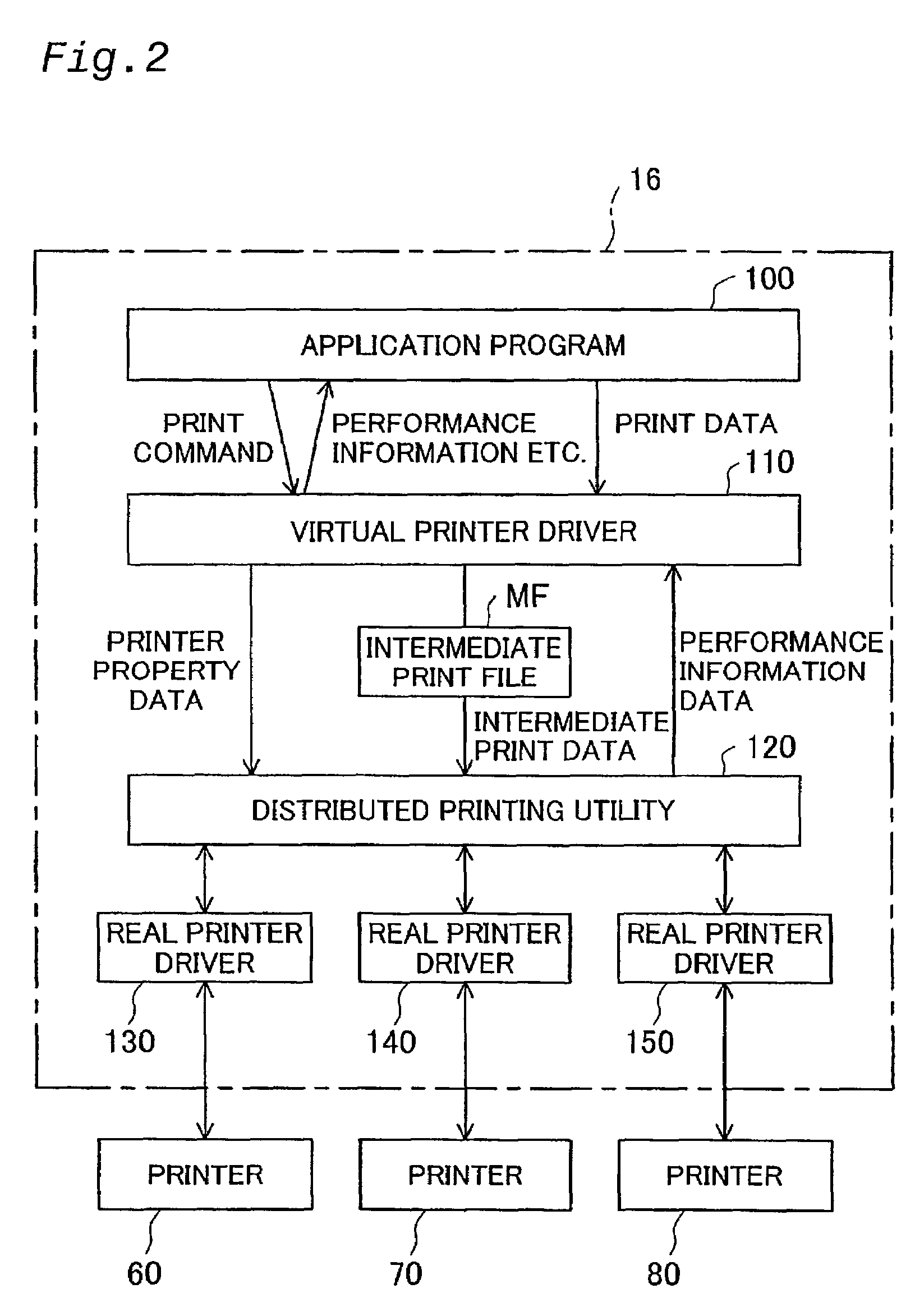
[0279]FIG. 37 is a block diagram showing the functions of a distributed printing utility 120C in the third embodiment. As illustrated, the distributed printing utility 120C includes an intermediate print data input module 121, a property data input module 122, an allocation specification module 123, an output data control module 124, a printer setting module 125, an output command output module 126, a performance information input module 127, a final print data...


PUM


Abstract

A technique for distributed printing that ensures favorable operability within a sufficiently short time. The procedure first generates intermediate print data and executes the parallel rendering process by time sharing to sequentially convert page data on the first page of the intermediate print data into data adequate for the printers. Transmission of final print data converted for the first printer is carried out in parallel with the rendering process for the second printer. In a similar manner, transmission of converted final print data to the second printer and third printers is carried out in parallel with the rendering process for the next printer. The parallel rendering process sequentially converts page data on the second page of the intermediate print data into data adequate for the printers. Subsequently, the parallel rendering process sequentially converts page data on the third page of the intermediate print data into data adequate for the printers.

Description

TECHNICAL FIELD[0001]The present invention relates to a technique of outputting print data of interest, which are to be printed, to multiple printers in a distributive manner.BACKGROUND ART[0002]Recent advancement of the computer network enables a plurality of printers to be readily connected to one information processing apparatus like a personal computer. In the structure where one information processing apparatus connects with multiple printers, print data generated by the information processing apparatus may be output to the respective printers in a distributive manner. When there is a large mass of print data, it takes an undesirably long time to complete printing with only one printer Output of the print data to multiple printers in a distributive manner desirably shortens the total time required for printing.[0003]The prior art technique has a variety of operatability-related problems discussed below.Problems Regarding Operatability of Printing[0004]The prior art technique re...

Claims


Application Information

Patent Timeline
Patent Type & Authority Patents(United States)
IPC IPC(8): G06F3/12
CPCG06F3/1215G06F3/1247G06F3/1245G06F3/124
Inventor IWATA, FUMIHIKOASAKAWA, MASASHISATO, AKIHIROMOCHIDA, AKIRATOGASHI, KOKI
Owner SEIKO EPSON CORP
Why Eureka
Try Eureka