Vibratory damped guide lever for a working device

a working device and vibration damping technology, which is applied in the direction of mechanical vibration separation, roads, ways, etc., can solve the problems of increasing stresses, affecting the decoupling of the vibrations of the working device, and the most present overlaying stress is not suitable for achieving good damping characteristics, so as to avoid an undesired noise development, the effect of further improving the vibration damping of the guide lever

Inactive Publication Date: 2007-02-13
BOMAG
View PDF13 Cites 4 Cited by
  • Summary
  • Abstract
  • Description
  • Claims
  • Application Information

AI Technical Summary

Benefits of technology

[0015]A stop can be arranged additionally in the working position in accordance with another embodiment of the invention. The stop is used for the purpose of fixing the height of the guide lever so as to make it ergonomically advantageous to the operator. It is possible to design the stop such that it is also adjustable. Thus it is possible to individually adjust the working position of the guide lever.
[0016]Another embodiment of the invention uses a stop whose elements determining the end position are provided additionally with damping elements and/or the stop itself is damped. The damping elements can also be arranged on the contact zone of the guide lever. In this way the vibration damping of the guide lever can be further improved while simultaneously avoiding an undesired noise development between the guide lever and the stop.
[0017]The overall

Problems solved by technology

The overlaying stress that is mostly present (pressure, shearing, torsion) is not suitable for achieving good damping characteristics.
However, the disadvantage of the layout that provided technical protection from vibrations is that the steering efforts have to be transferred to the working device via the damping elements

Method used


Image

  • Vibratory damped guide lever for a working device
  • Vibratory damped guide lever for a working device
  • Vibratory damped guide lever for a working device

Examples


Embodiment Construction

.

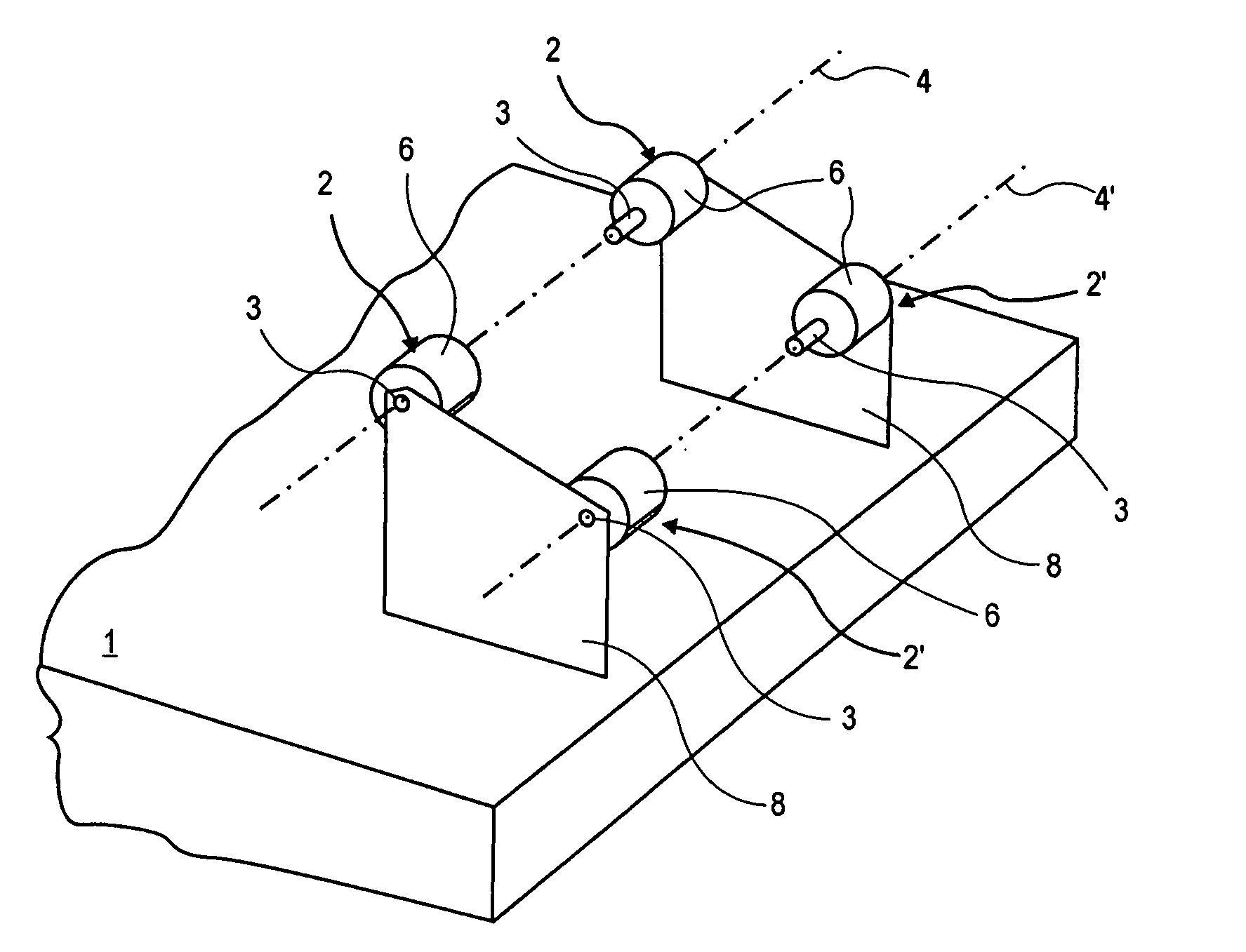
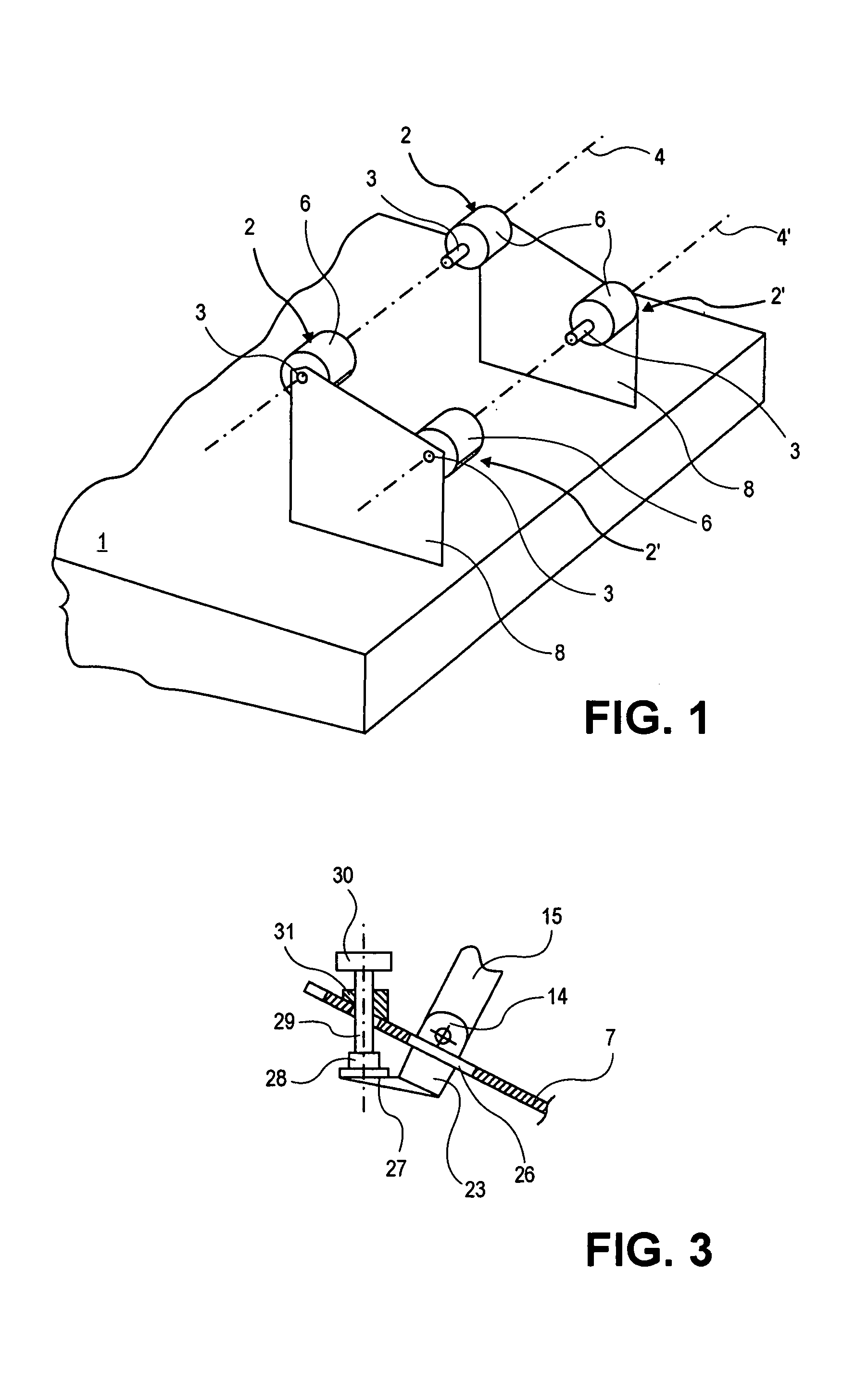
[0024]FIG. 1 is a schematic illustration of an automotive working device 1 for dynamic soil compaction. The working device 1 is operated by an operator who walks along the device. Examples of such devices include a vibrating plate, a unicycle vibrating roller or a double vibrating roller. Four connection points are arranged on its framework. They are each provided with a bearing 2,2′ for a hand-operated guide lever (drawbar) 15 (FIGS. 2, 4, 5) for the operator. The bearings 2, 2′ are arranged in the corners of a rectangle.

[0025]As FIG. 1 illustrates, two bearings 2, 2′ are designed on bearing blocks 8 that are located on the side of the machine. The bearings are provided with attachment bolts 5 for holding the damping elements 6 via which the guide lever 15 is connected to the working device 1. The damping elements 6 are aligned pairwise along the imaginary diagonal axes 4, 4′ that extend parallel to the cross direction of the working device 1. The distance between the bearings 2, ...


PUM


Abstract

The invention concerns a hand-operated working device such as, for example, vibrating plates and vibrating rollers for soil compaction with a guide lever that is arranged on the working device such that it is vibratory damped, can be adjusted in its working height, and can be folded and fixed in a transport position. It has an elastic damping element on each of the four junctures distributed in the arrangement. All four damping elements are connected on the side turned away from the device to a console. The guide lever is arranged on the console.

Description

CROSS REFERENCE TO RELATED APPLICATIONS[0001]This application claims priority to German Patent Application Serial No. 102004009989.8, filed Mar. 1, 2004 and German Patent Application Serial No. 102004015588.7 filed Mar. 30, 2004 titled, VIBRATORY DAMPED GUIDE LEVER FOR A WORKING DEVICE, the disclosure of which is incorporated by reference in its entirety.FIELD OF THE INVENTION[0002]The invention concerns a hand-operated, automotive working device, for example, a vibrating plate, a vibrating roller and such for soil compaction with a vibratory damped guide lever.BACKGROUND OF THE INVENTION[0003]Small-structured, automotive working devices for soil compaction of the afore-mentioned type are controlled by one operating person who walks with the working device. The operator steers the device in the direction of movement and controls the device functions by means of a guide lever. The guide lever is usually designed as a height-adjustable drawbar. The control and operating elements are a...

Claims


Application Information

Patent Timeline
IPC IPC(8): E02D7/18E02D3/046E02D3/068F16F15/08B06B1/04E01C19/28E01C19/35E01C19/38E02D31/02
CPCE01C19/283E02D31/02E01C19/38E01C19/35
Inventor KREMER, KLAUS
Owner BOMAG
Why Eureka
Try Eureka