Heat-insulating container and apparatus for producing the same

a technology for heat-insulating containers and apparatus, which is applied in the field of heat-insulating containers, can solve the problems of unnecessarily large thickness of containers, high production cost, and upper portion, and achieves stable heat-insulating properties, high grade design, and high degree of freedom in printing.

Inactive Publication Date: 2007-02-13
DAI NIPPON PRINTING CO LTD
View PDF30 Cites 41 Cited by
  • Summary
  • Abstract
  • Description
  • Claims
  • Application Information

AI Technical Summary

Benefits of technology

[0016]One of objects of the present invention, which was made in order to solve the above-mentioned problems, is to provide a heat-insulating container made of paper, which ha

Problems solved by technology

The above-described container having the cup body surrounded with the heat-insulating corrugated member has a problem that the container has an unnecessarily larger thickness even in the upper portion thereof, which is not brought into contact with a hand, regardless of the cross-sectional shape of the heat-insulating member.
The irregularity on the outer surface of the container may become obstacle to a high grade design to be given to the container, and characters, patterns and the like printed on the surface thereof may be made unclear and vague, thus causing problems.
The container obtained in accordance with such a proposal has an uneconomic problem that the high production cost is required, an external appearance problem that the heat-insulating container may has the irregular bottom and the narrow projections and recesses or the embossed portions may be visible from the bottom, and an unhygienic problem that dust or a liquid may enter gaps of these portions.
When the container is actually held at the central portion of the side wall thereof with a hand, the sleeve 55 may however easily be warped inward to decrease the capacity of the heat-insulating space, thus deteriorating the heat-insulating property.
However, in such structure, since the rib is formed into a round or triangular shape in its cross-

Method used


Image

  • Heat-insulating container and apparatus for producing the same
  • Heat-insulating container and apparatus for producing the same
  • Heat-insulating container and apparatus for producing the same

Examples


Embodiment Construction

[0182]The preferred embodiments of the present invention will be described below more in detail with reference to the attached drawings.

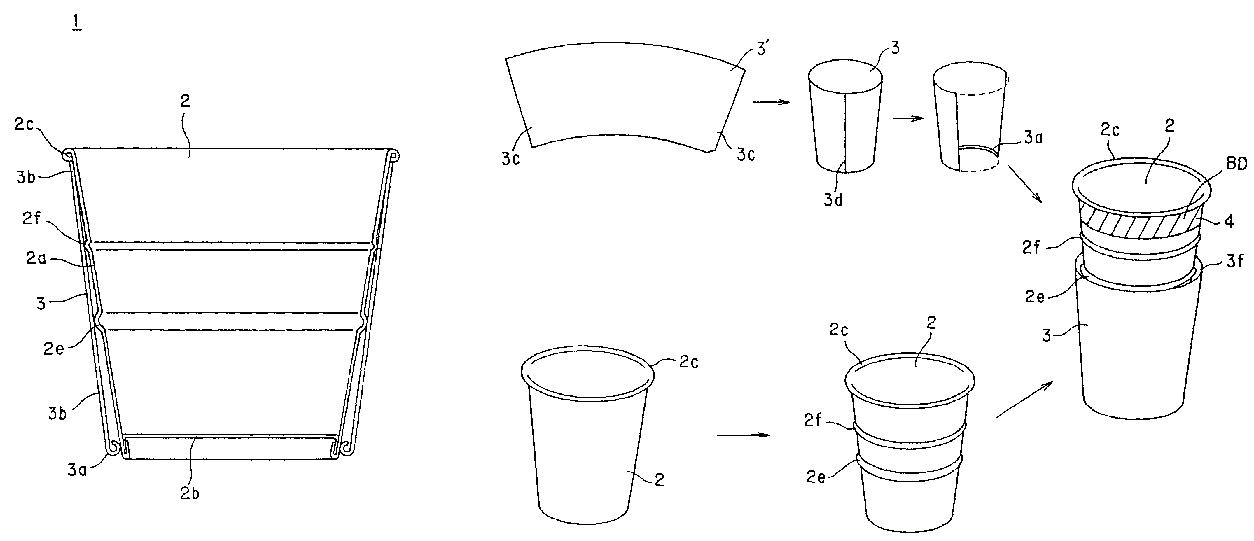
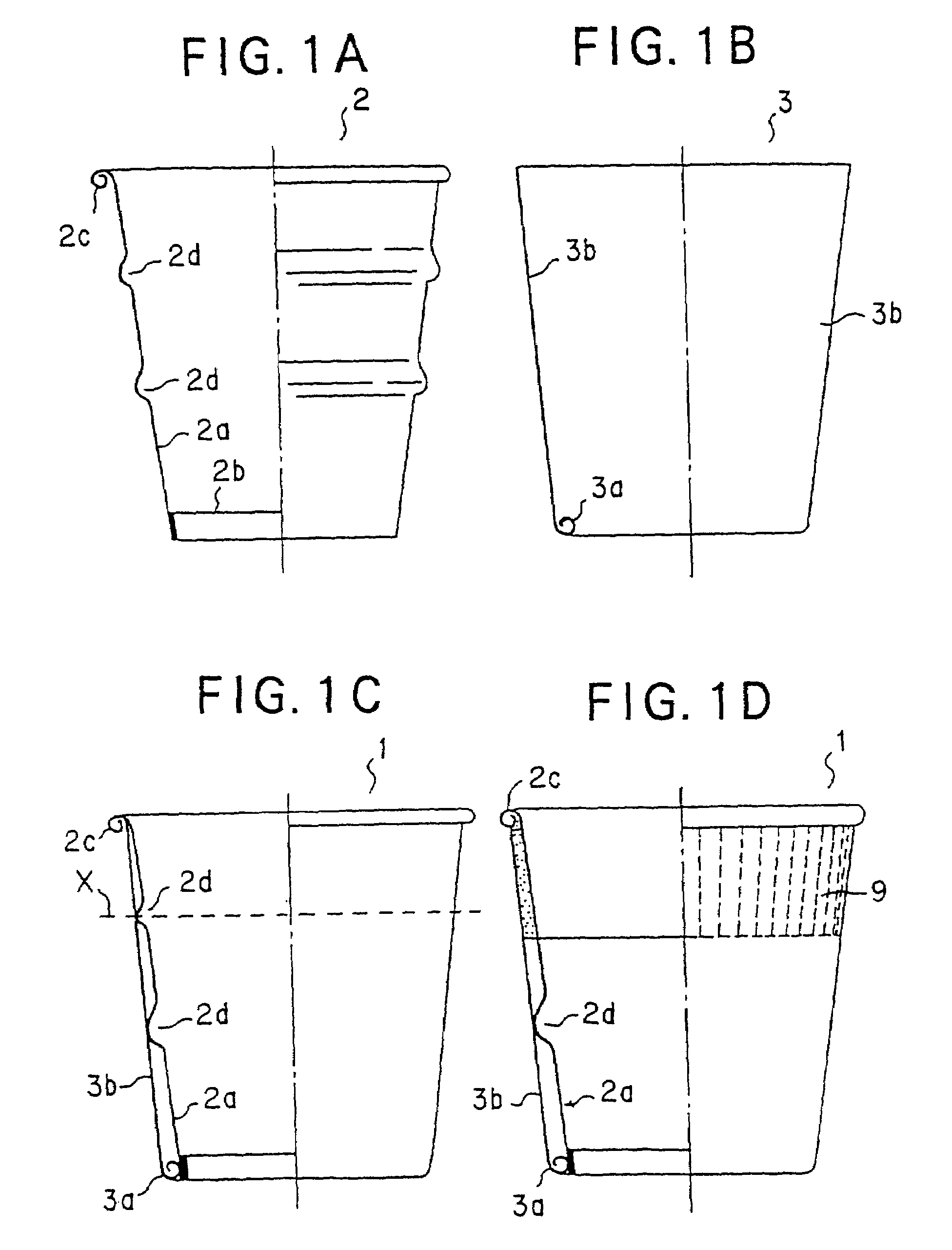
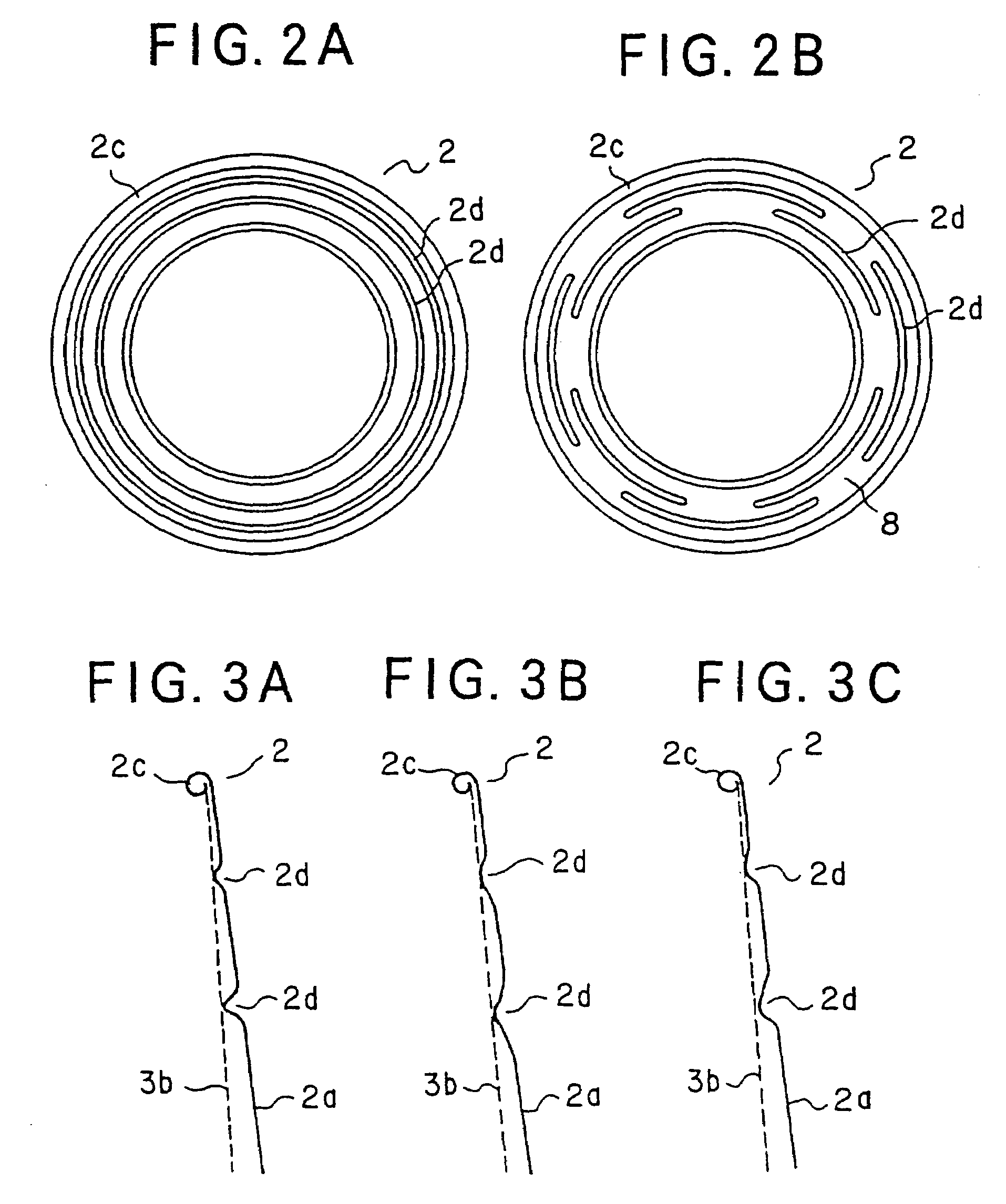
[0183]FIGS. 1A to 1D are descriptive views illustrating structure of a heat-insulating container of the present invention.

[0184]The heat-insulating container 1 of the present invention is composed of a cup body 2 made of paper, which has at the upper portion of the side wall 2a thereof an outward curled portion 2c and at the middle portion of the side wall 2a horizontal ribs 2d, 2d, and is provided with a bottom 2b, as shown in FIG. 1A, and an inverse-frustoconical paper sleeve 3, which has the upper and lower opening ends and is provided at its lower end with an inward curled portion 3a. The upper end portion of the sleeve 3 is joined by means of an adhesive agent with the outer periphery of the side wall 2a of the cup body 2, which is adjacent to the outward curled portion 2c, as shown in FIG. 1C. The inner surface of the inward curled portion 3a ...


PUM


Abstract

A heat-insulating container is used for an instant dried food and is excellent in heat-insulating property, design and economy. The container comprises a paper cup body with a bottom, which has an inner surface coated with a polyolefin resin and is provided with an outward curled portion formed at an upper opening end of the cup body and at least one horizontal rib formed on a side wall of the cup body so as to project outward therefrom; and an inverse-frustoconical paper sleeve provided with an inward curled portion formed at a lower end of the sleeve. The cup body and the sleeve are integrally combined with each other so that an upper end of the sleeve is joined to an outer periphery of the side wall of the cup body, which is adjacent to the outward curled portion of the cup body, and an inner surface of the inward curled portion of the sleeve is joined to an outer periphery of a lower portion of the side wall of the cup body.

Description

[0001]This application is a division of U.S. Ser. No. 09 / 269,594 filed Mar. 29, 1999 now U.S. Pat. No. 6,663,926, which U.S. application is hereby incorporated herein by reference.TECHNICAL FIELD [0002]The present invention relates to a heat-insulating container made of paper, which is used for an instant dried food to be become eatable by pouring boiled water over it and an apparatus suitable for producing at least one part of the container.BACKGROUND ART [0003]As a heat-insulating container made paper mainly used for instant dried Chinese noodles, there has widely been used a container in which a paper cup body surrounded over its outer periphery with a heat-insulating corrugated member subjected to a process so as to make an alternate arrangement of narrow projections and recesses in the longitudinal direction of the cup body.[0004]In Japanese Patent Provisional Publication No. H8-113274, there is proposed a heat-insulating container in which a change in its cross-sectional shape...

Claims


Application Information

Patent Timeline
IPC IPC(8): B31C1/00B31B15/00B31B45/00B65D3/22B65D81/38
CPCB31B1/25B31B1/32B31B7/00B31B15/00B31B17/00B31B45/00B31F1/0038B65D3/22B65D81/3869B31F1/10B31B1/28Y10T428/1303B31B2201/2604B31B2201/2612B31B2201/2695B31B2203/00B31B2217/003B31B2217/0069B31B2217/062B31B2217/082B31B2217/108B31B2201/257B31B50/256B31B50/28B31B50/32B31B50/81B31B2105/00B31B2105/0022B31B2110/10B31B2110/20B31B2120/002B31B2120/407B31B2120/501B31B2120/70
Inventor OKUSHITA, MASATAKAYAMADA, KAZUKIHIRAI, YUICHIMOCHIZUKI, YOICHIENDO, KENICHI
Owner DAI NIPPON PRINTING CO LTD
Why Eureka
Try Eureka