
Syringe and method of using

a syringe and plunger technology, applied in the field of syringe and method of use, can solve the problems of the difficulty of handling syringes and plungers currently in use, and the inability to prevent the introduction of contaminants, so as to preserve sterility and reduce the likelihood of contamination of pre-filled or pre-dosed syringes

Inactive Publication Date: 2007-02-13
GRAY ROBIN SCOTT
View PDF20 Cites 22 Cited by
  • Summary
  • Abstract
  • Description
  • Claims
  • Application Information

AI Technical Summary

Benefits of technology

These designs effectively prevent contamination of the syringe barrel, maintain sterility, and reduce the risk of medication leakage, ensuring safer handling of biohazardous materials like chemotherapy drugs and radioactive pharmaceuticals.

Problems solved by technology

Although not encouraged, inadvertent contact of the plunger shaft typically occurs with the hands, fingers, or gloves during the preparation of a solution.
While a handle portion is usually located on the rearward end portion of the plunger to aid an individual in sliding the plunger into and out of the syringe barrel, larger syringes are typically difficult to handle using only one hand, or even both hands, because of the syringe size, plunger length, and friction created by surface area contact between the internal wall surfaces of the syringe barrel and the plunger piston surface.
Syringes and plungers currently in use do little to discourage the introduction of contaminants onto the plunger shaft and inner syringe barrel surface.
The current syringes also suffer from problems of piston failure or detachment of the piston from the forward end of the plunger shaft causing loss of the seal between the piston and the inner surfaces of the syringe barrel.
When this occurs, medication in the syringe barrel leaks or flows out of the syringe barrel rearward end opening and onto the hands, fingers, gloves, and work surface.
When the material is blood or the medication or additive being used to prepare the solutions is a biohazard material such as certain chemotherapy drugs, acids, or radioactive pharmaceuticals, the safety of the individual working with the material is compromised because of exposure to and contact with the hazardous material.
An additional problem which plagues current syringe designs is the problem resulting from pulling the forward end of the plunger and piston to close to the rearward end opening of the syringe barrel cavity leading to accidental separation of the plunger from the barrel.
Also, when the piston and forward end of the plunger are withdrawn along the syringe barrel cavity and positioned close to the rearward syringe barrel opening, the plunger shaft and medication in the syringe cavity is in increased jeopardy of contamination.
Additionally, any rocking motion caused to the plunger shaft while in this position tends to compromise the seal between the piston and the syringe barrel inner surface causing leaking of the medication.

Method used


Image

  • Syringe and method of using
  • Syringe and method of using
  • Syringe and method of using

Examples


second embodiment

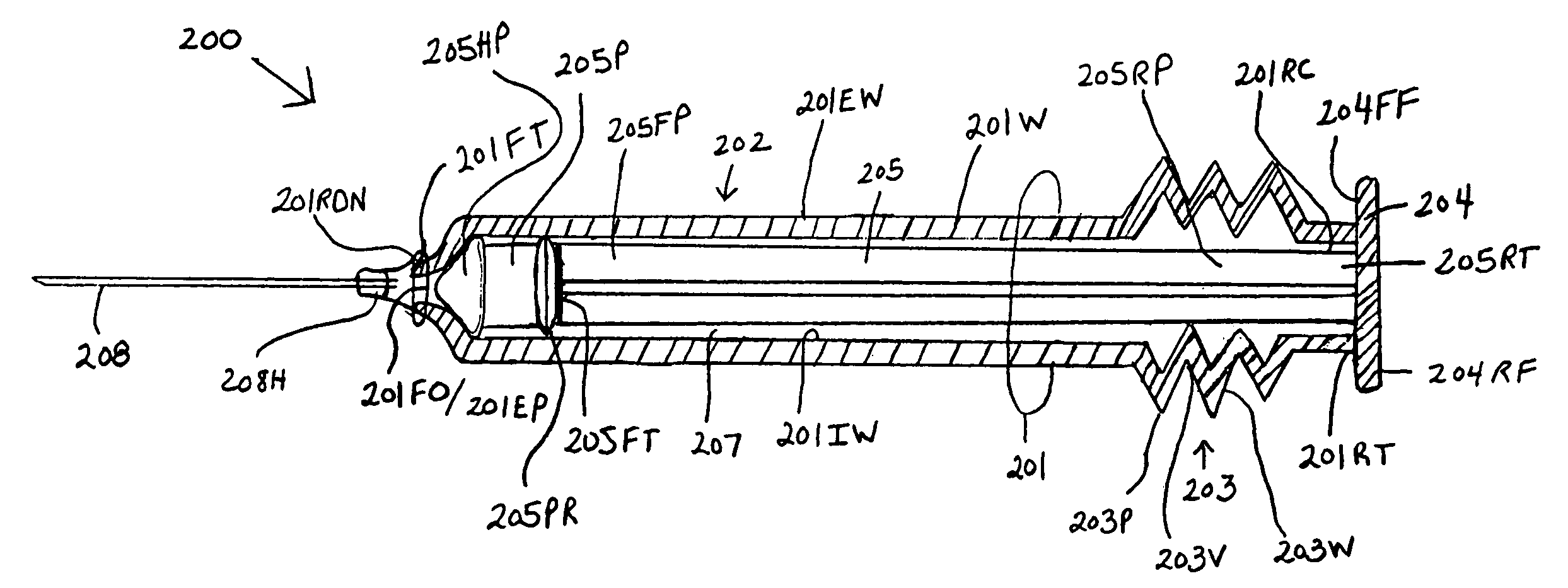
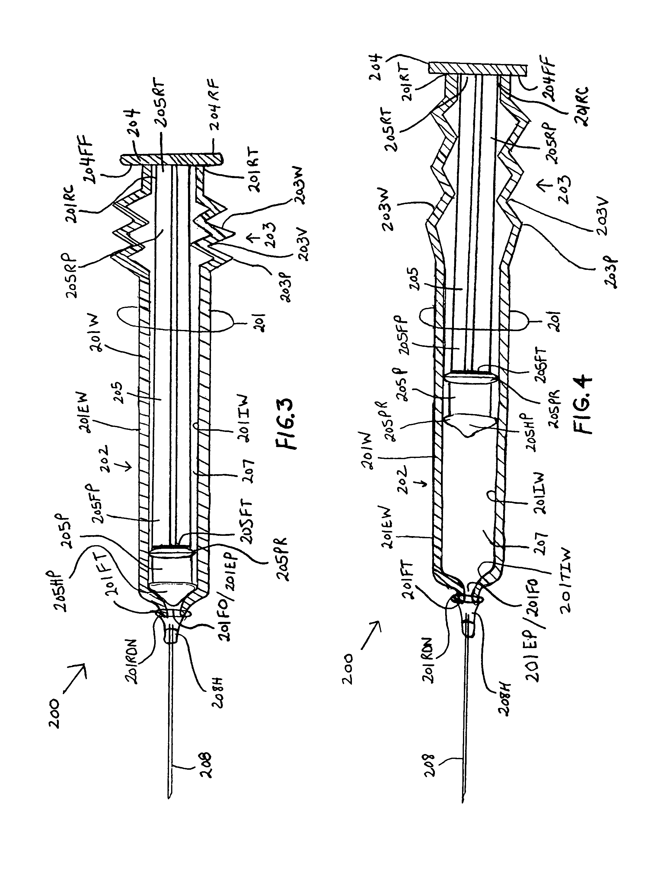
[0052]the instant invention, as shown by FIG. 3, illustrates a new and improved syringe 200 formed of a cylindrical syringe barrel 201 and a cylindrical plunger member 205. The syringe barrel 201 is formed with a straight segment 202 and a corrugated segment 203. The straight segment 202 is located on the forward end section of the syringe barrel 201 and the corrugated segment 203 is located at the rearward end section of the syringe barrel 201. The rearward end terminus 201 RT of the syringe barrel 201 is molded to the forward face surface 204FF of a plunger handle member 204. The rearward end terminus 205RT of the plunger shaft 205 is centrally molded to the forward face surface 204FF of the plunger handle member 204. A rearward end portion 205PP of the plunger shaft body 205 is enclosed or surrounded by the corrugated segment 203 of the syringe barrel 201. The syringe barrel 201 has a forward open end 201FO and a rearward closed end 201RC. The rearward closed end 201RC is closed ...

third embodiment

[0055]the instant invention, as shown by FIGS. 5, 6A and 6B, illustrates a new and improved syringe 300 formed of a cylindrical syringe barrel 301 and a cylindrical plunger member 302. The syringe barrel 301 and the plunger member 302 have mating concentric plunger member and syringe barrel walls 302W and 301W, respectively. The plunger member 302 has a wall 302W having an open-end 3020E and a closed end 302CE. The closed end 302CE of the plunger member 302 has a flat bottom floor structure 304 forming a cup-shaped inner cavity. The flat bottom floor structure 304 has forward and rearward face surfaces 304FF and 304RF, respectively. The flat bottom floor structure 304 can be molded continuous with the plunger member cylindrical walls 302W. The inside diameter of the plunger member 302 is constant along its length. The forward face surface 304FF of the flat bottom floor structure 304 has molded thereto the rearward end terminus 305RT of a plunger shaft 305. The plunger shaft 305 is c...

fourth embodiment

[0060]the instant invention, as shown by FIGS. 7, 8A and 8B, illustrates a new and improved syringe 400 formed of cylindrical concentric syringe barrels 401OB and 401IB and a cylindrical plunger member 402. The plunger member 402 has a wall 402W with a forward open-end 402FO and a rearward closed end 402RC. The rearward closed end 402RC of the plunger member 402 has a flat bottom floor structure 403 forming a cup. It is noted that other shapes can be used for the bottom floor structure; and thus, the shapes are not restricted to flat. The flat bottom floor structure 403 has forward end and rearward end face surfaces 403FF and 403RF, respectively. The flat bottom floor structure 403 can be molded continuous with the walls of the plunger member 402W. The inside diameter of the plunger member walls 402W is constant along the length of the plunger member 402. The forward end face surface 403FF of the flat bottom floor structure 403 has molded thereto the rearward end terminus 404RT of a...


PUM


Abstract

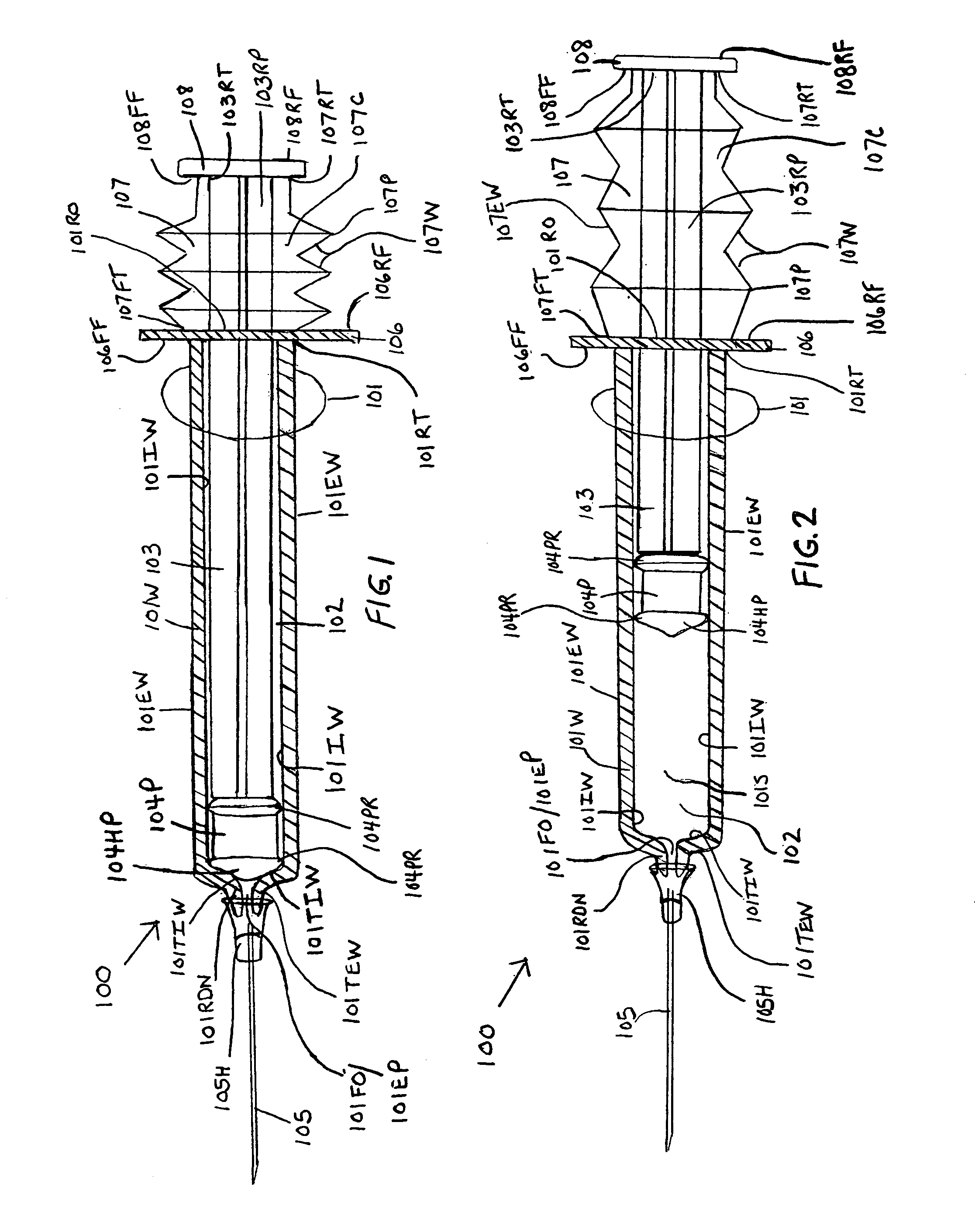
Syringes and methods of using are described which protect the syringe barrel cavity from contaminants. A first syringe is formed with a corrugated sheath which encloses the plunger and space between the rearward end face surface of the syringe barrel handle member and the forward face of the plunger handle member. A second syringe is formed with a syringe barrel having a straight segment and a corrugated segment having the forward face of the plunger handle member molded to the rearward terminus of the corrugated segment of the syringe barrel. A third syringe is formed from mating syringe barrel and plunger member walls. The walls of the mating syringe barrel and plunger member are concentric and slide relative to each other while maintaining an enclosure around the plunger shaft. A fourth syringe is formed from inner and outer concentric syringe barrel walls mating with the walls of a plunger member. The mating walls are concentric and slide relative to each other while maintaining an enclosure around the plunger shaft. A fifth syringe is formed with an end cap contaminant shield having an extension wall that is mated with the rearward end opening of the syringe barrel cavity. Alternatively, the end cap contaminant shield can be provided with a flat design without the extending wall and is bonded or molded to the rearward end terminus of the syringe barrel. The end cap contaminant shield designs are provided with an opening defining the shape of the cross-section of the plunger shaft.

Description

[0001]This application is a Divisional of U.S. application Ser. No. 10 / 057,519 filed on Jan. 24, 2002. U.S. Pat. No. 6,830,564 B2.BACKGROUND OF THE INVENTION[0002]Syringes are used by medical personnel to withdraw blood from patients, inject intravenous medications into patients, inject intramuscular medications into patients, prepare irrigation solutions, prepare dialysis fluids, prepare intravenous pushes, prepare bolus fluids, prepare intravenous fluids for parenteral injection, and prepare oral dose medications. Personnel trained to prepare solutions, pushes, or other fluids for injection prepare the solutions within a laminar flow hood or a vertical flow hood using aseptic technique. The hood provides a work area which reduces the probability of contaminants being introduced into the intravenous admixtures or other solutions during their preparation. Vertical flow hoods and biohazard hoods additionally reduce the probability of escape of biohazard materials being used from the ...

Claims


Application Information

Patent Timeline
Patent Type & Authority Patents(United States)
IPC IPC(8): A61M5/00A61M5/178A61M5/31A61M5/315
CPCA61M5/3135A61M5/31511A61M5/315A61M5/3137A61M2005/3121A61M5/502A61M2005/3139
Inventor GRAY, ROBIN SCOTT
Owner GRAY ROBIN SCOTT
Learn More