System for quick disconnect of torch from power and gas supply unit

a technology of power supply unit and torch, which is applied in the field of welding or heating system to achieve the effect of simple and inexpensiv

Inactive Publication Date: 2007-02-13
ILLINOIS TOOL WORKS INC
View PDF7 Cites 23 Cited by
  • Summary
  • Abstract
  • Description
  • Claims
  • Application Information

AI Technical Summary

Benefits of technology

[0012]The invention is directed to a torch cable in which both the electrical connection and the pneumatic connection can be made concurrently in one motion by coupling the end of the torch cable to the exterior of the supply unit. The coupling further includes a quick disconnect feature. The torch cable coupling is simple and inexpensive, using standard off-the-shelf components. The end of the cable comprises various components that are overmolded to form an electrically insulative body, e.g., made of urethane rubber compound. This molded body incorporates strain relief, is water resistant, protects the electrical plug, and stabilizes the electrical contacts. The invention allows gas, power and control to be combined in one assembly. In one embodiment of the invention, the pneumatic quick disconnect coupling is used as a latching mechanism for the entire assembly. The torch cable can be disconnected from the supply unit by simply releasing the quick disconnect coupling and then pulling the end of the torch cable away from the supply unit. The pneumatic connector and the electrical plug form keying means by their orientation. The pneumatic connector on the supply unit can be either self-closing or straight through when the torch cable is uncoupled.

Problems solved by technology

A quick disconnect connector is advantageous in that it simplifies torch removal but is expensive to make.

Method used


Image

  • System for quick disconnect of torch from power and gas supply unit
  • System for quick disconnect of torch from power and gas supply unit
  • System for quick disconnect of torch from power and gas supply unit

Examples


Embodiment Construction

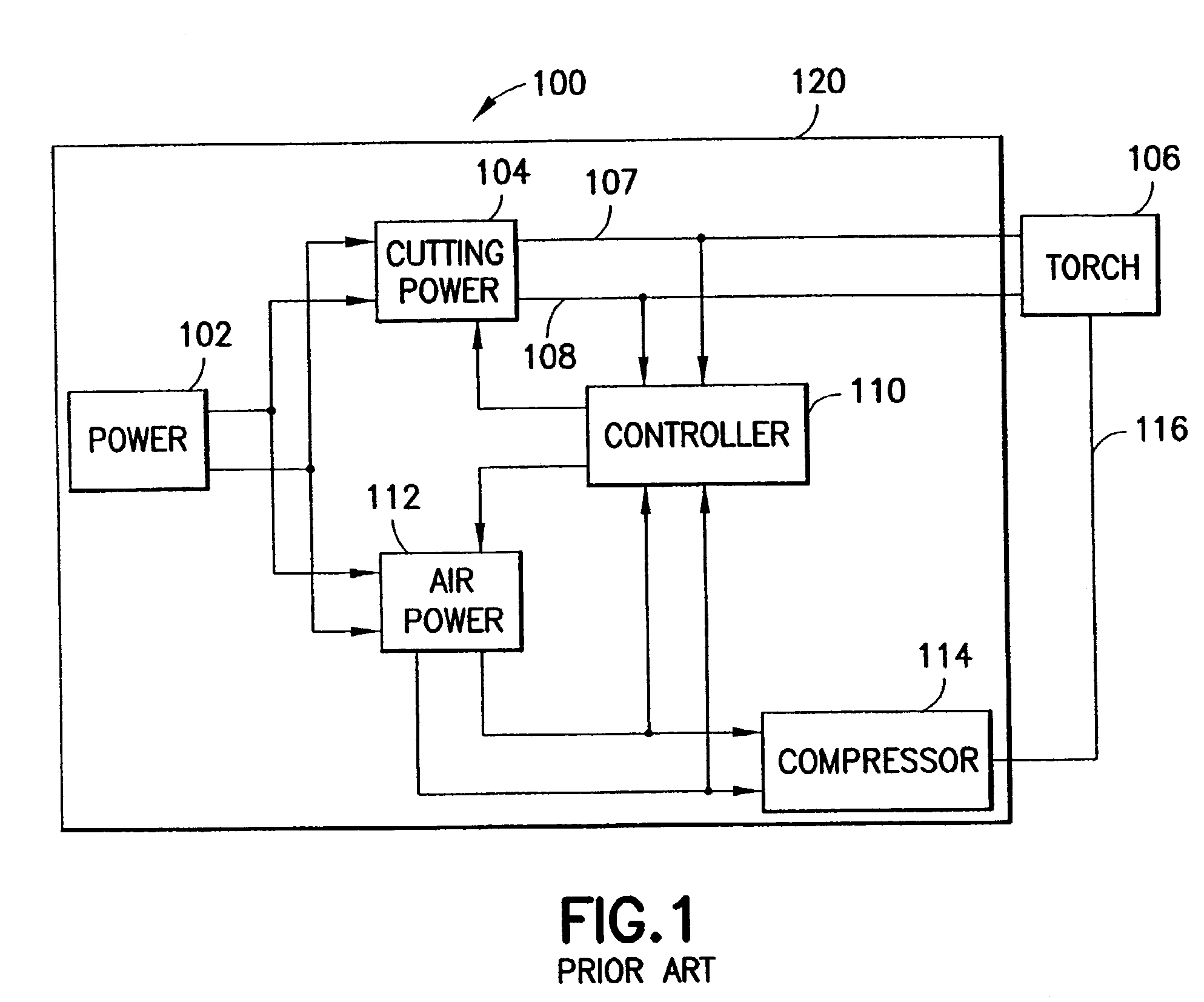
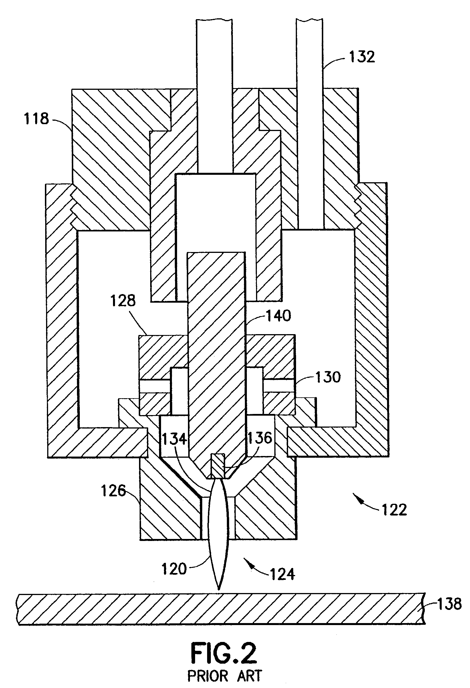
[0039]The present invention is concerned with the coupling of a plasma arc cutting torch or an arc welding torch to a power supply unit and structures for accomplishing such coupling. The invention is not limited in any sense to a particular torch or to a particular power supply unit. For the sake of illustration, a known plasma arc cutting system will be described with reference to FIG. 1 and a known plasma arc torch will be described with reference to FIG. 2. However, it should be appreciated that the quick disconnect feature of the present invention can be used in other plasma arc cutting systems with other plasma arc torches as well as in arc welding systems.

[0040]FIG. 1 (taken from U.S. Pat. No. 6,194,6130) shows a known plasma cutter 100 having an air compressor 114 disposed in a housing 120. Plasma cutter 100 includes a power source 102 that provides power to a cutting power supply 104 and air power supply 112. Power source 102 may include a transformer core and a primary win...


PUM

PropertyMeasurementUnit
currentaaaaaaaaaa
electricallyaaaaaaaaaa
lengthaaaaaaaaaa

Abstract

A torch cable in which both the electrical connection and the pneumatic connection can be made concurrently in one motion by coupling the end of the torch cable to the exterior of the supply unit. The coupling further includes a quick disconnect feature. The torch cable coupling is simple and inexpensive, using standard off-the-shelf components. The end of the cable comprises various components that are overmolded to form an electrically insulative body, e.g., made of urethane rubber compound. This molded body incorporates strain relief, is water resistant, protects the electrical plug, and stabilizes the electrical contacts. Gas, power and control are combined in one assembly. The pneumatic quick disconnect coupling is used as a latching mechanism for the entire assembly. The torch cable can be disconnected from the supply unit by simply releasing the quick disconnect coupling and then pulling the end of the torch cable away from the supply unit. The pneumatic connector and the electrical plug form keying means by their orientation.

Description

BACKGROUND OF THE INVENTION[0001]This invention generally relates to welding or heating systems. In particular, the invention relates to plasma arc cutting units.[0002]Plasma arc cutting is a process in which an electric arc is used to cut a metallic workpiece. Generally, plasma arc cutting uses an electric arc between an electrode and the metal to be cut. The arc creates a plasma that cuts the metallic workpiece. Plasma cutters are often used in applications such as building maintenance (structural or HVAC) where they are carried from job to job, and thus are preferably highly portable.[0003]A typical prior art plasma arc cutter includes a. power supply, an air supply and a plasma torch. A plasma torch is used to create and maintain the arc and the plasma jet that perform the cutting. A plasma cutting power supply receives an input voltage (from a power line or generator) and provides an output voltage to a pair of output terminals, one of which is the electrode and the other of wh...

Claims


Application Information

Patent Timeline
Patent Type & Authority Patents(United States)
IPC IPC(8): B23K10/00B23K9/32
CPCB23K9/323
Inventor HERRES, KENNETH F.
Owner ILLINOIS TOOL WORKS INC
Why Eureka
Try Eureka