Outdoor-installed power conditioner device

a power conditioner and installation method technology, applied in the direction of power cables, electrical apparatus casings/cabinets/drawers, insulated conductors, etc., can solve the problems of increased manufacturing cost, decreased workability of attaching lids, and worker's accidental touch or damage of power converters, so as to reduce the number of members required

Inactive Publication Date: 2007-02-13
SHARP KK +1
View PDF28 Cites 20 Cited by
  • Summary
  • Abstract
  • Description
  • Claims
  • Application Information

AI Technical Summary

Benefits of technology

[0025]A first object of the invention is to provide an enclosure for an outdoor-installed power conditioner which effectively protects the outdoor-installed power conditioner from an external factor such as rainwater or dust and is excellent in appearance and workability during maintenance.
[0026]A second object of the invention is to provide an outdoor-installed power conditioner which efficiently exhausts air taken into the conditioner via a fan, prevents rainwater from infiltrating into the conditioner from an intake vent and an exhaust vent, and is excellent in workability during maintenance of the fan.
[0027]A third object of the invention is to provide an outdoor-installed power conditioner capable of securing an exhaust channel reliably and preventing rainwater infiltration into its inside.

Problems solved by technology

Such an increase in the number of screws 204 causes problems of an increase in manufacturing cost and a decrease in workability of attaching lid 203 to outer case 202.
If the work for connecting the interconnections is carried out in such a situation, the worker may accidentally touch or damage power converter 206.
However, in conventional outdoor-installed power conditioner 301, the direction in which the air blown out by fan 316 flows is relatively perpendicular to the direction in which the air exhausted from exhaust vent 306 flows, and thus the air taken in by fan 316 is not efficiently exhausted to the outside of outer case 302.
Due to the above-mentioned reasons, efficiency for cooling power converter 335 in heat sink 311 may be reduced, leading to the possibility of an increase in the temperature of power converter 335 not being suppressed sufficiently.
Performing such a work takes time and effort, degrading workability during the maintenance of fan 316.
Further, when trash such as fallen leaves accumulates between the rear face of the enclosure and the outer wall surface, the exhaust vent may be clogged by the trash.

Method used


Image

  • Outdoor-installed power conditioner device
  • Outdoor-installed power conditioner device
  • Outdoor-installed power conditioner device

Examples


first embodiment

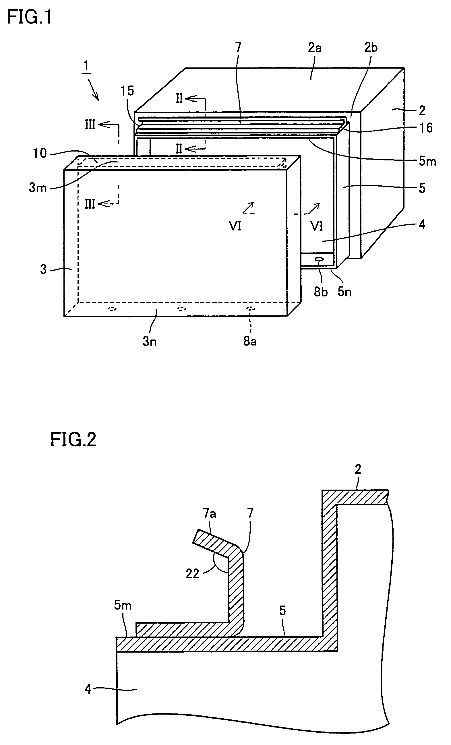
[0078]FIG. 1 is a perspective view showing an enclosure for an outdoor-installed power conditioner in a first embodiment of the present invention. Referring to FIG. 1, an enclosure 1 housing a power converter installed outdoors includes an outer case 2 and a lid 3. Outer case 2 and lid 3 are made of a metal material. Outer case 2 and lid 3 are formed so as to have equal-sized attachment faces to eliminate difference in level on the surface of enclosure 1, improving the appearance of enclosure 1.

[0079]An opening 4 is provided in a front face 2b, one of the four side faces of outer case 2. Along the periphery of opening 4, an outer peripheral portion 5 is formed so as to project from front face 2b. On a top face 5m of outer peripheral portion 5, a plate member 7 is provided extending from one end 15 to the other end 16 of top face 5m. In a bottom face 5n of outer peripheral portion 5, a plurality of screw holes 8b for fastening lid 3 to outer case 2 are formed. It is to be noted that,...


PUM


Abstract

An enclosure is formed of an outer case and a lid. The outer case includes a first projecting strip portion provided on a top face side of the outer case and on an outer peripheral portion defining an opening, and extending to project outwardly from the outer case, and the lid includes a second projecting strip portion provided at a position facing the first projecting strip portion. With the opening of the outer case closed with the lid, the first and second projecting strip portions make close contact with each other along a direction in which these portions extend. This structure can protect the inside from an external factor such as rainwater or dust.

Description

[0001]This application is the US national phase of international application of PCT / JP03 / 07832 filed 19 Jun. 2003 which claims priority of JP 2002-182759 filed Jun. 24, 2002; JP 2002-208637 filed Jul. 17, 2002; and 2003-155221 filed May 30, 2003, the entire contents of which are hereby incorporated by reference.TECHNICAL FIELD[0002]The present invention relates to an outdoor-installed power conditioner converting direct current (DC) power produced by an independent DC power supply into alternating current (AC) power to supply the power to a general AC load for home and business use or to an existing commercial power system.BACKGROUND ART[0003]A solar battery is known as a simple and clean energy source without emitting toxic substances. Exposed to sunlight, it operates as a DC power supply and outputs DC power. A power conditioner for photovoltaic power generation system serves to convert DC power generated by a solar battery into AC power to supply the power to a general AC load or...

Claims


Application Information

Patent Timeline
Patent Type & Authority Patents(United States)
IPC IPC(8): H05K7/20A47B81/00H02B1/28H05K5/06
CPCH02B1/28H05K7/20154H05K5/063
Inventor NAKATA, HIROFUMIHIROSE, NAOTOSAKAMOTO, YUKITAKA
Owner SHARP KK
Why Eureka
Try Eureka