Vapor-compression refrigerant cycle system with refrigeration cycle and Rankine cycle

a technology of vapor-compression refrigerant cycle and rankine cycle, which is applied in the direction of refrigeration components, machines/engines, lighting and heating apparatus, etc., can solve the problems of inability to effectively operate single compressors, difficulty in performing rankine cycle or normal vapor-compression refrigerant cycle normal operation in practice, and difficulty in effective recovery of external waste heat by heat exchangers

Inactive Publication Date: 2007-02-20
DENSO CORP +1
View PDF7 Cites 22 Cited by
  • Summary
  • Abstract
  • Description
  • Claims
  • Application Information

AI Technical Summary

Benefits of technology

[0009]In view of the above-described problems, it is an object of the present invention to provide a vapor-compression refrigerant cycle system provided with a Rankine cycle and a refrigeration cycle that can be effectively operated.
[0010]It is another object of the present invention to provide a vapor-compression refrigerant cycle system with a Rankine cycle that prevents a pumping efficiency of a liquid pump from being reduced.
[0011]According to the present invention, a vapor-compression refrigerant cycle system includes a compressor for sucking and compressing refrigerant, a radiator provided at a refrigerant discharge side of the compressor for cooling the refrigerant, a gas-liquid separator for separating the refrigerant from the radiator into gas refrigerant and liquid refrigerant, a decompression device for decompressing the liquid refrigerant flowing out of the gas-liquid separator, an evaporator for evaporating the refrigerant after being decompressed in the decompression device, a heater for heating the refrigerant, a liquid pump for supplying the liquid refrigerant in the gas-liquid separator to the heater, a cooling means for cooling the liquid refrigerant to be sucked into the liquid pump, an energy recovery unit for expanding the refrigerant flowing out of the heater to recover thermal energy in the refrigerant from the heater, and a switching means for switching between a refrigeration cycle where the evaporator has a refrigeration capacity and a Rankine cycle where the energy recovery unit recovers the thermal energy. In the vapor-compression refrigerant cycle system, when the refrigeration cycle is set, the refrigerant is circulated in this order of the compressor →the radiator→the gas-liquid separator→the decompression device→the evaporator→the compressor. Further, when the Rankine cycle is set in the vapor-compression refrigerant cycle system, the refrigerant is circulated in this order of the gas-liquid separator the liquid pump→the heater→the energy recovery unit the radiator the gas-liquid separator, and the cooling means cools the liquid refrigerant to be introduced into the liquid pump in the Rankine cycle. Accordingly, a super-cooling degree of the liquid refrigerant sucked into the liquid pump can be effectively reduced, and it can prevent the sucked liquid refrigerant of the liquid pump from being evaporated (boiled). Thus, the efficiency of the liquid pump can be effectively improved.
[0012]Preferably, the radiator is connected to the refrigerant discharge side of the compressor through a refrigerant circuit, the switching means includes a switching member that is disposed in the refrigerant circuit to shut a refrigerant flow from the refrigerant discharge side of the compressor to the radiator in the Rankine cycle, and the liquid pump is provided to supply the liquid refrigerant to the heater while bypassing the switching member in the Rankine cycle. Therefore, both of the refrigeration cycle and the Rankine cycle can be effectively operated.
[0018]More preferably, an additional pump is provided for supplying the liquid refrigerant in the gas-liquid separator into a suction side of the liquid pump. In this case, the pressure of liquid refrigerant at the suction side of the liquid pump can be increased, and it can further prevent the liquid refrigerant from being boiled in the liquid pump. The additional pump can be integrated with the gas-liquid separator. In this case, at least a suction side of the additional pump is disposed in the liquid refrigerant of the gas-liquid separator. Further, the liquid pump and the additional pump can be integrated with the gas-liquid separator.
[0020]Further, according to another aspect of the present invention, a vapor-compression refrigerant cycle system includes a compressor for sucking and compressing refrigerant, a radiator provided at a refrigerant discharge side of the compressor for cooling the refrigerant, a decompression device for decompressing refrigerant flowing out of the radiator, an evaporator for evaporating the refrigerant after being decompressed in the decompression device, a refrigerant shutting unit disposed in a refrigerant circuit between the radiator and a refrigerant discharge side of the compressor to shut a refrigerant flow from the refrigerant discharge side of the compressor to the radiator, a heater for heating the refrigerant, a refrigerant supply means for supplying refrigerant to the heater while bypassing the refrigerant shutting unit, and an energy recovery unit for expanding the refrigerant flowing out of the heater to recover thermal energy in the refrigerant from the heater. In the vapor-compression refrigerant cycle system, when a refrigeration cycle where the evaporator has a refrigeration capacity is set, the refrigerant is circulated in this order of the compressor→the radiator→the decompression device→the evaporator→the compressor. On the other hand, when a Rankine cycle where the energy recovery unit recovers the thermal energy is set, the refrigerant shutting unit shuts the refrigerant flow from the refrigerant discharge side of the compressor to the radiator, and the refrigerant is circulated by the refrigerant supply means in this order of the heater→the energy recovery unit→the radiator→the heater. Thus, the Rankine cycle can be accurately operated, and a switching operation between the refrigeration cycle and the Rankine cycle can be readily performed.

Problems solved by technology

Thus, when the heat exchanger is configured so as to be adaptable as the evaporator, it becomes difficult for the heat exchanger to effectively recover external waste heat by functioning as the heater.
Accordingly, in the case of using a scroll type compressor, it is impossible to effectively operate the single compressor so as to function as an expansion device.
Therefore, either normal operation of a Rankine cycle or normal operation of the vapor-compression refrigerant cycle cannot be performed in practice.
In this case, a pump efficiency of the liquid pump is decreased, and cavitation is readily caused in the liquid pump.

Method used


Image

  • Vapor-compression refrigerant cycle system with refrigeration cycle and Rankine cycle
  • Vapor-compression refrigerant cycle system with refrigeration cycle and Rankine cycle
  • Vapor-compression refrigerant cycle system with refrigeration cycle and Rankine cycle

Examples


first embodiment

(First Embodiment)

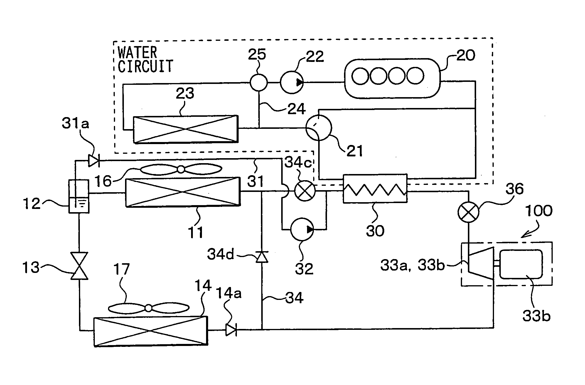
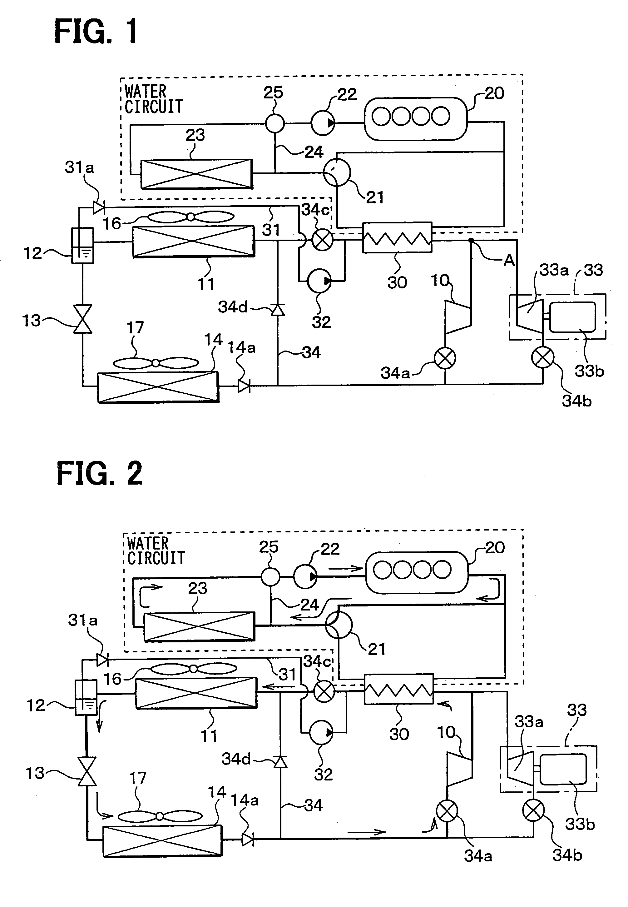
[0047]In the first embodiment, a Rankine vapor-compression refrigerant cycle system is a vapor-compression refrigerant cycle system provided with a Rankine cycle and a refrigeration cycle. Further, the Rankine vapor-compression refrigerant cycle system of the present invention is typically used for a vehicle. FIG. 1 is a schematic diagram of the Rankine vapor-compression refrigerant cycle system according to the present embodiment.

[0048]The vapor-compression refrigerant cycle system provided with the Rankine cycle, according to the present embodiment, is intended to recover energy from waste heat generated by an engine 20 serving as a heat engine for generating a motive power for running, and also to utilize cold and heat derived from the vapor-compression refrigerant cycle, for the purpose of air conditioning. The vapor-compression refrigerant cycle system provided with the Rankine cycle is described hereinafter.

[0049]A compressor 10 is for sucking and compressing...

second embodiment

(Second Embodiment)

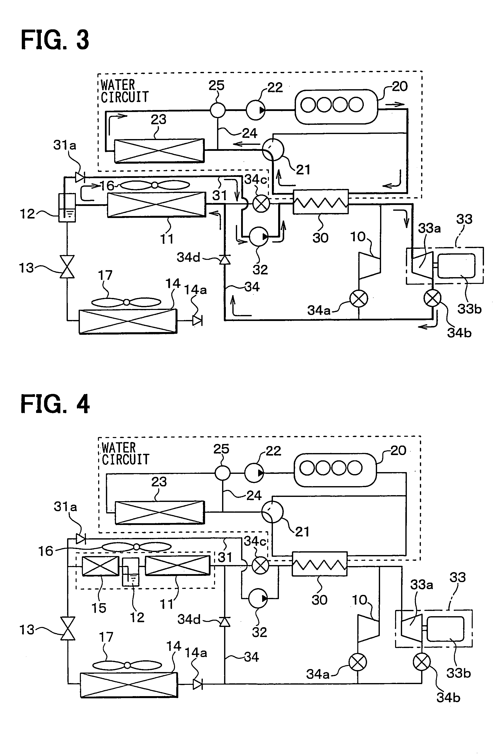
[0074]The second embodiment of the present invention will be now described with reference to FIG. 4. In the second embodiment, as shown in FIG. 4, there is provided a super-cooler 15 for further cooling a liquid phase refrigerant separated in the gas-liquid separator 12, to thereby enhancing a super-cooling degree of the refrigerant.

[0075]In the second embodiment, the first bypass circuit 31 through which liquid refrigerant is supplied to the liquid pump 32 is connected to a refrigerant outlet side of the super-cooler 15. The super-cooler 15 further cools the liquid phase refrigerant from the gas-liquid separator 12. Therefore, it can prevent the liquid phase refrigerant, to be sucked into the liquid pump 32 from being evaporated, thereby preventing damage due to cavitation from occurring to the liquid pump 32, and preventing resultant deterioration in pump efficiency. However, as in the case of the first embodiment, the first bypass circuit 31 at the side of the ...

third embodiment

(Third Embodiment)

[0077]The third embodiment of the present invention will be now described with reference to FIG. 5. In the third embodiment, as shown in FIG. 5, refrigerant paths are changed over by using a changeover valve 35 in place of the switching valves 34a to 34c. More specifically, the changeover valve 35 opens one of two refrigerant paths, and closes the other thereof.

[0078]Further, FIG. 5 shows a case where the present embodiment is applied to the first embodiment, however, the present embodiment may be applied to the second embodiment. In the third embodiment, the other parts are similar to those of the above-described first or second embodiment.


PUM


Abstract

A vapor-compression refrigerant cycle system with a refrigeration cycle and a Rankine cycle includes a compressor, a radiator, a gas-liquid separator, a decompression device and an evaporator. In the vapor-compression refrigerant cycle system, a liquid pump is disposed for supplying the liquid refrigerant in the gas-liquid separator to a heater for heating the refrigerant, a cooling means is provided for cooling the liquid refrigerant to be sucked into the liquid pump, and an energy recovery unit for expanding the refrigerant flowing out of the heater is disposed to recover thermal energy in the refrigerant from the heater. When the Rankine cycle is set so that the energy recovery unit recovers the thermal energy, the cooling means cools the liquid refrigerant to be sucked into the liquid pump. Therefore, pumping efficiency of the liquid pump can be effectively improved.

Description

CROSS REFERENCE TO RELATED APPLICATION[0001]This application is based on Japanese Patent Applications No. 2003-17667 filed on Jan. 27, 2003, No. 2003-139896 filed on May 19, 2003, No. 2003-395603 filed on. Nov. 26, 2003 and No. 2003-410094 filed on Dec. 9, 2003, the disclosure of which is incorporated herein by reference.FIELD OF THE INVENTION[0002]The present invention relates to a vapor-compression refrigerant cycle system provided with a Rankine cycle for recovering thermal energy and a refrigeration cycle for performing a cooling operation. The vapor-compression refrigerant cycle system is suitably used for an air conditioner for a vehicle.BACKGROUND OF THE INVENTION[0003]In a conventional vapor-compression refrigerant cycle system provided with a Rankine cycle, a compressor of a vapor-compression refrigerant cycle is used as an expansion device in a case where an energy recovery is performed by the Rankine cycle.[0004]For example, in a vapor-compression refrigerant cycle system...

Claims


Application Information

Patent Timeline
Patent Type & Authority Patents(United States)
IPC IPC(8): F25B1/00F25B27/00F25B43/00F02G5/04F25B1/04
CPCF02G5/04F25B27/00F25B1/04Y02T10/166F25B2400/23F25B2600/2507F25B2700/04F25B2400/04Y02T10/12F25B1/00
Inventor INABA, ATSUSHIYAMANAKA, YASUSHIIWANAMI, SHIGEKIBAN, KOICHIHISANAGA, SHIGERUHOTTA, TADASHIOZAKI, YUKIKATSUUCHIDA, KAZUHIDE
Owner DENSO CORP
Why Eureka
Try Eureka