Partially constrained ball and socket

a technology of ball and socket and partial restriction, which is applied in the field of provisional prosthesis instrumentation, can solve the problems of patient immobility, small percentage of hip joint implant procedures, and difficulty in precise alignmen

Active Publication Date: 2007-02-20
HOWMEDICA OSTEONICS CORP
View PDF25 Cites 38 Cited by
  • Summary
  • Abstract
  • Description
  • Claims
  • Application Information

AI Technical Summary

Benefits of technology

[0020]It is an object of the invention to provide a simplified metho

Problems solved by technology

This requires precise alignment and in some cases the precise alignment is difficult to obtain.
One problem with artificial joint implants, such as hip implants, is that there is a very small percentage of hip joint implant procedures using the semi-constrained construction which dislocate.
Such dislo

Method used


Image

  • Partially constrained ball and socket
  • Partially constrained ball and socket
  • Partially constrained ball and socket

Examples


Embodiment Construction

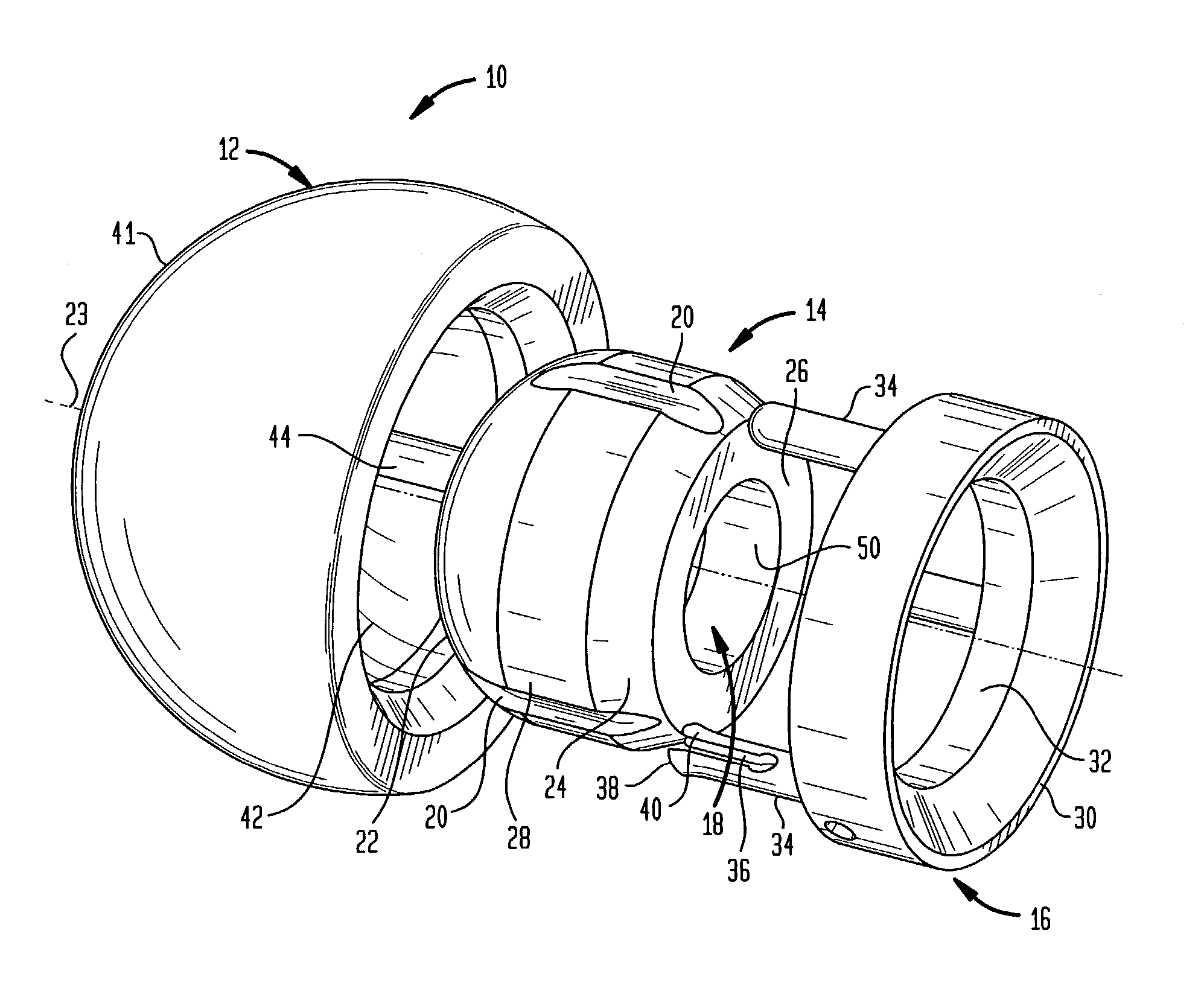
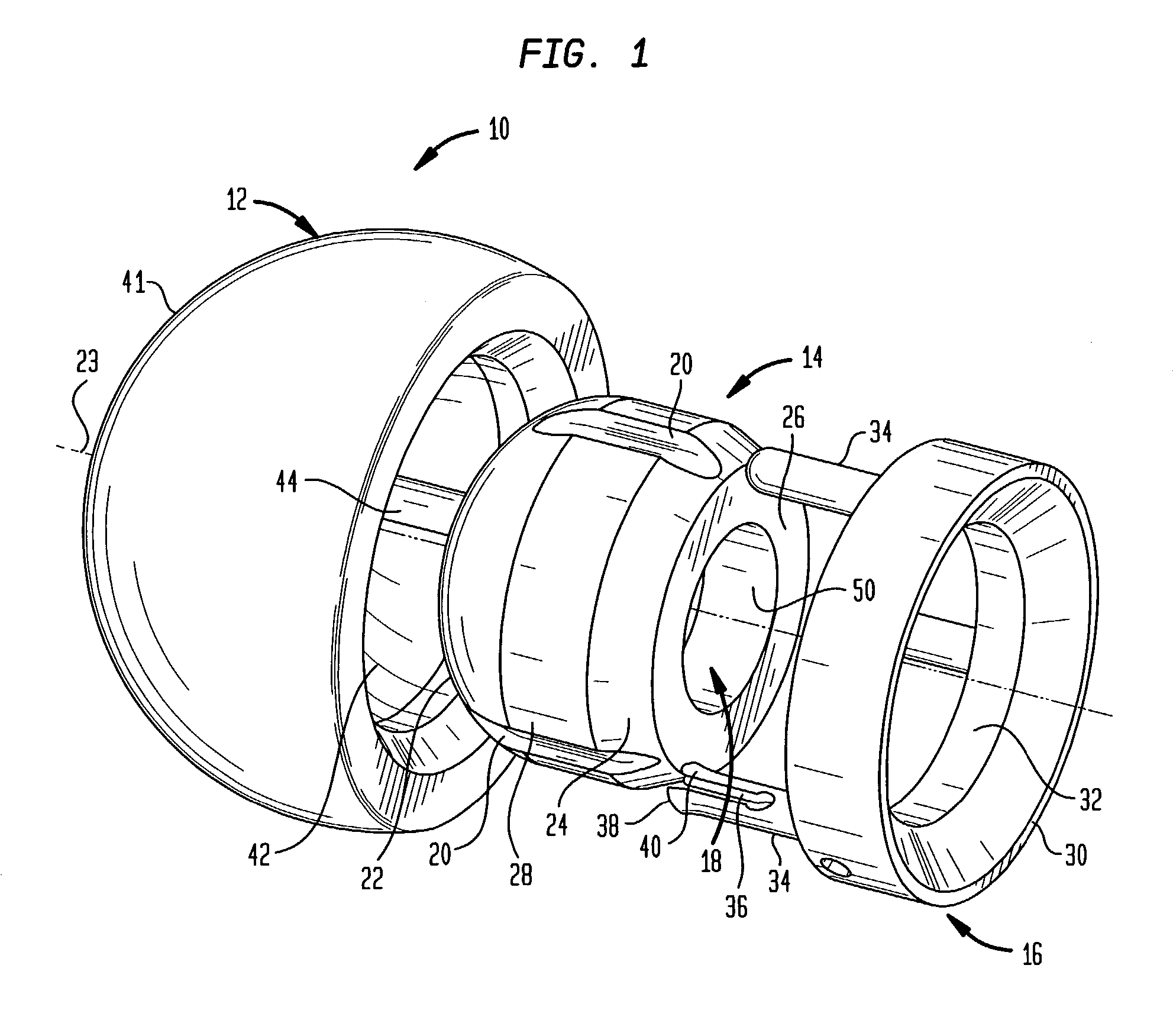
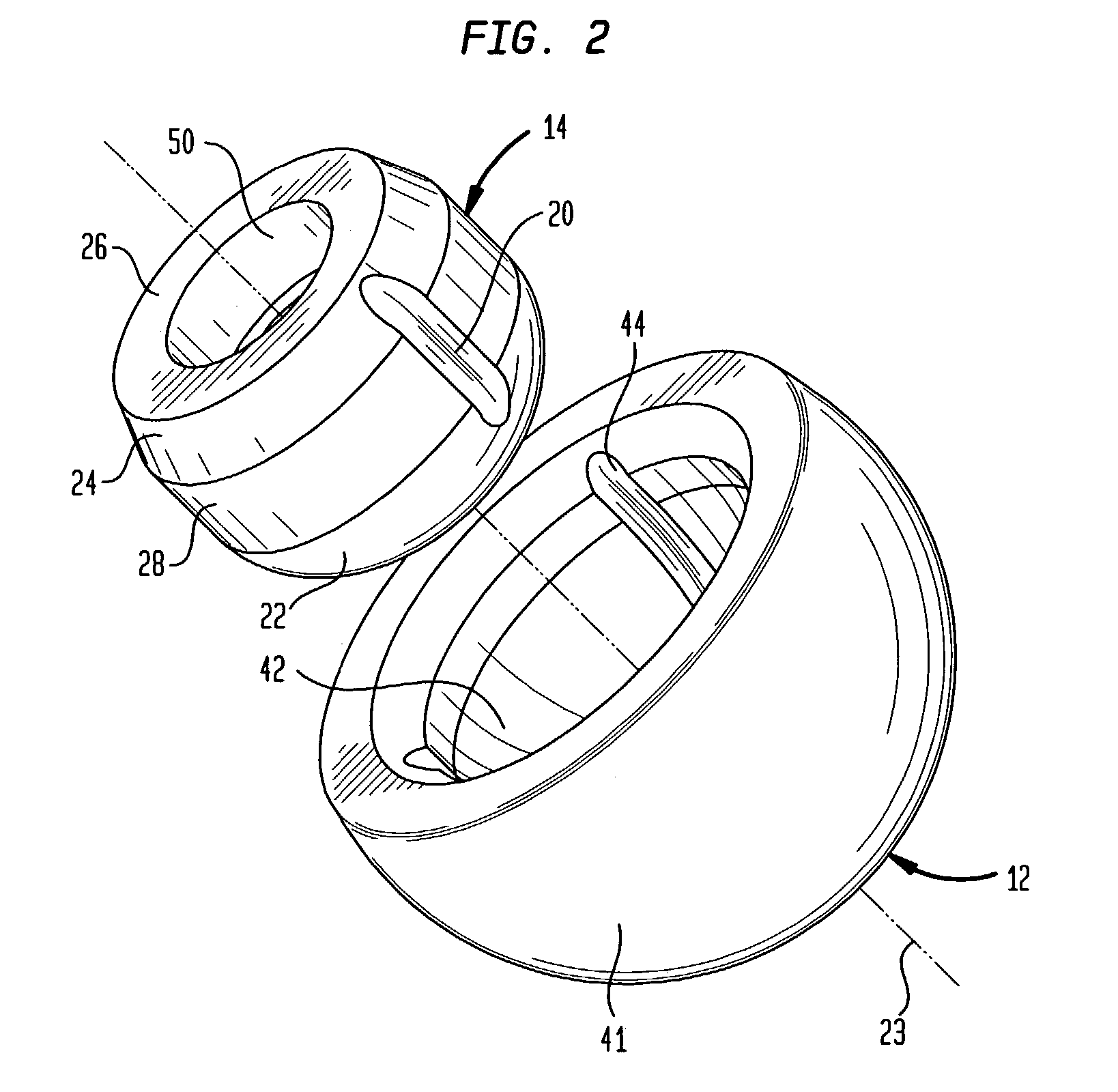
[0040]Referring to FIGS. 1–7 there is shown an exploded view of the device of the present invention which is utilized as a provisional head of a joint prosthesis. The device, generally denoted at 10, comprises a provisional or trial acetabulum contacting component 12, an inner component 14 and a locking element 16. In the preferred embodiment, the device 10 and inner component 14 is utilized in connection with a bipolar or unipolar hip implant which, as shown in FIG. 7, includes a femoral component 13 including a trunnion 15. Inner component 14 includes an opening 18 for receiving trunnion 15 of femoral component 13. In the preferred embodiment, the inner component 14 includes one or more grooves 20 extending parallel to the polar axis 23 of inner component 14. In the preferred embodiment, a series of three grooves 20 are used which are equally spaced around the circumference of inner component 14 and are thus are spaced at 120°. In the preferred embodiment, inner component 14 inclu...


PUM


Abstract

A provisional prosthesis used during trial fitting of a bipolar or unipolar joint prosthesis such as a hip acetabular component. The provisional prostheses include an outer provisional shell component having an interior part-spherical surface having an open end with at least one recess extending from said open end into said interior surface. An inner component, such as a head for femoral component, is provided which has a part-spherical outer surface for articulation with respect to the part-spherical inner surface. The outer surface has at least one recess aligned with a polar axis of the inner component and the outer component has an inner surface with at least one recess which can be aligned with a recess on the inner component. A locking assembly, including a pin, is provided which can be inserted into the aligned grooves to rotationally lock the inner and outer components together. In order to keep the inner component from disengaging with the outer component, the outer component has an inner part-spherical surface which extends beyond the equator and the inner component has a flat cord formed around the circumference thereof which has a diameter less than or equal to the diameter of the opening in the outer component so that the head component can be placed inside and rotated and be constrained within the outer component throughout the range-of-motion of the implant.

Description

BACKGROUND OF THE INVENTION[0001]The present invention relates to a set of provisional prosthesis instrumentation, and more particularly to instrumentation which is suitable for use in hip hemiarthroplastly procedures. In such procedures, the proximal portion of the femur is replaced with a suitable prosthetic hip joint implant or implant assembly which will mate or articulate directly with the natural acetabulum (as opposed to mating with a prosthetic acetabular joint implant component).[0002]The present invention also relates to an articulated prosthesis comprising a first articulating portion having a part-spherical bearing surface for engaging the acetabulum and a second inner part-spherical articulation surface and a second articulating component having an outer part-spherical bearing surface adapted to engage the second inner part-spherical bearing surface of the first component. More particularly, the invention relates to a prosthetic hip joint comprising a component for cont...

Claims


Application Information

Patent Timeline
IPC IPC(8): A61F2/32A61F2/00A61F2/30A61F2/36A61F2/46
CPCA61F2/4684A61F2250/0064A61F2002/30367A61F2002/30382A61F2002/30495A61F2002/30497A61F2002/305A61F2002/30596A61F2002/30604A61F2002/30607A61F2002/30616A61F2002/30774A61F2002/3208A61F2002/3611A61F2002/3621A61F2002/3631A61F2002/365A61F2002/4629A61F2002/4641A61F2220/0025A61F2220/0033A61F2250/006A61F2250/0062A61F2002/30332A61F2002/30331A61F2002/30594
Inventor DOONEY, TOM
Owner HOWMEDICA OSTEONICS CORP
Why Eureka
Try Eureka