Optical imaging apparatus
a technology of optical imaging and optical tubes, applied in the field of optical imaging apparatus, can solve the problems of inability to perform scrubbing and sterilization necessary for use in the body cavity, no probe detachment means, and organism damage, and achieve the effect of stable connection
- Summary
- Abstract
- Description
- Claims
- Application Information
AI Technical Summary
Benefits of technology
Problems solved by technology
Method used
Image
Examples
first embodiment
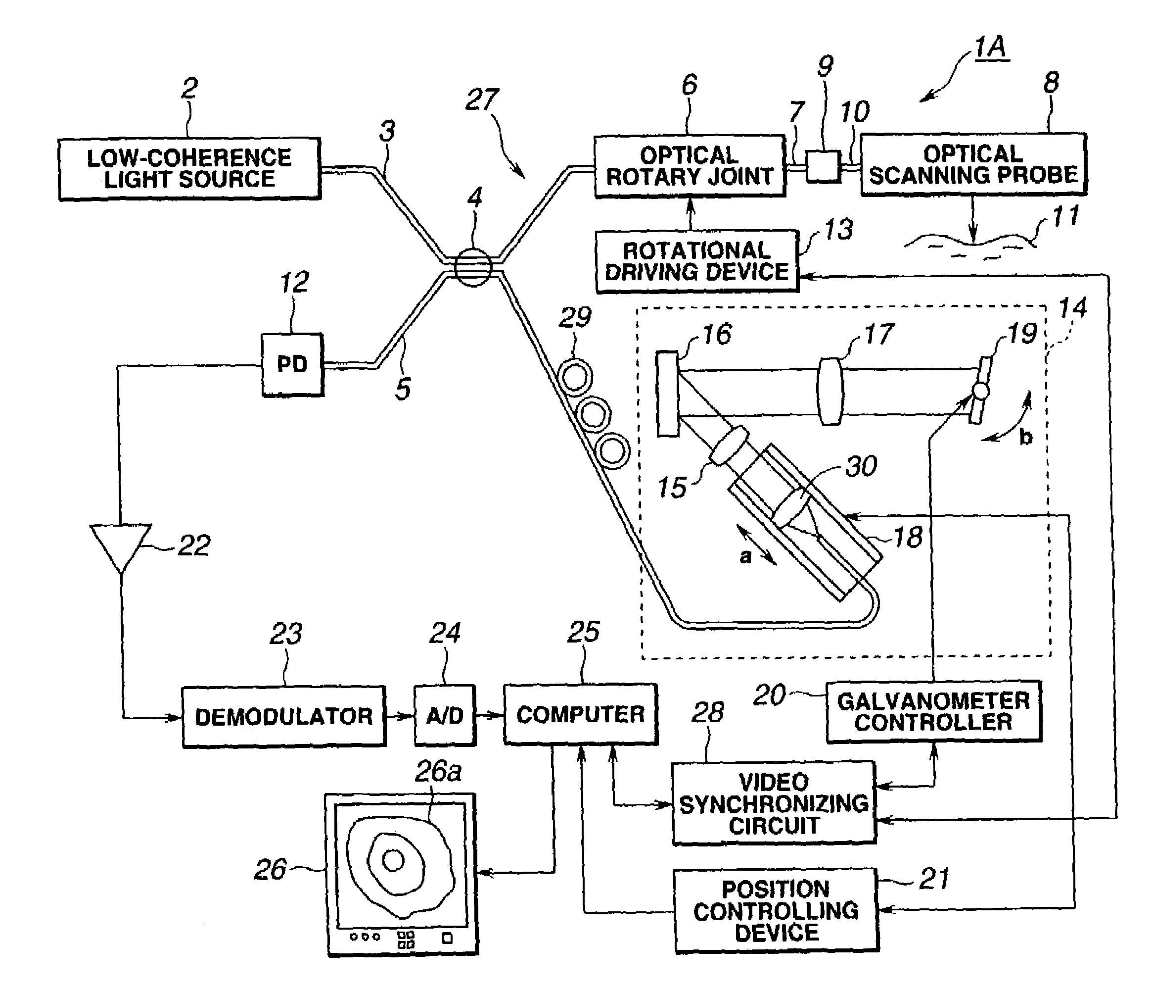
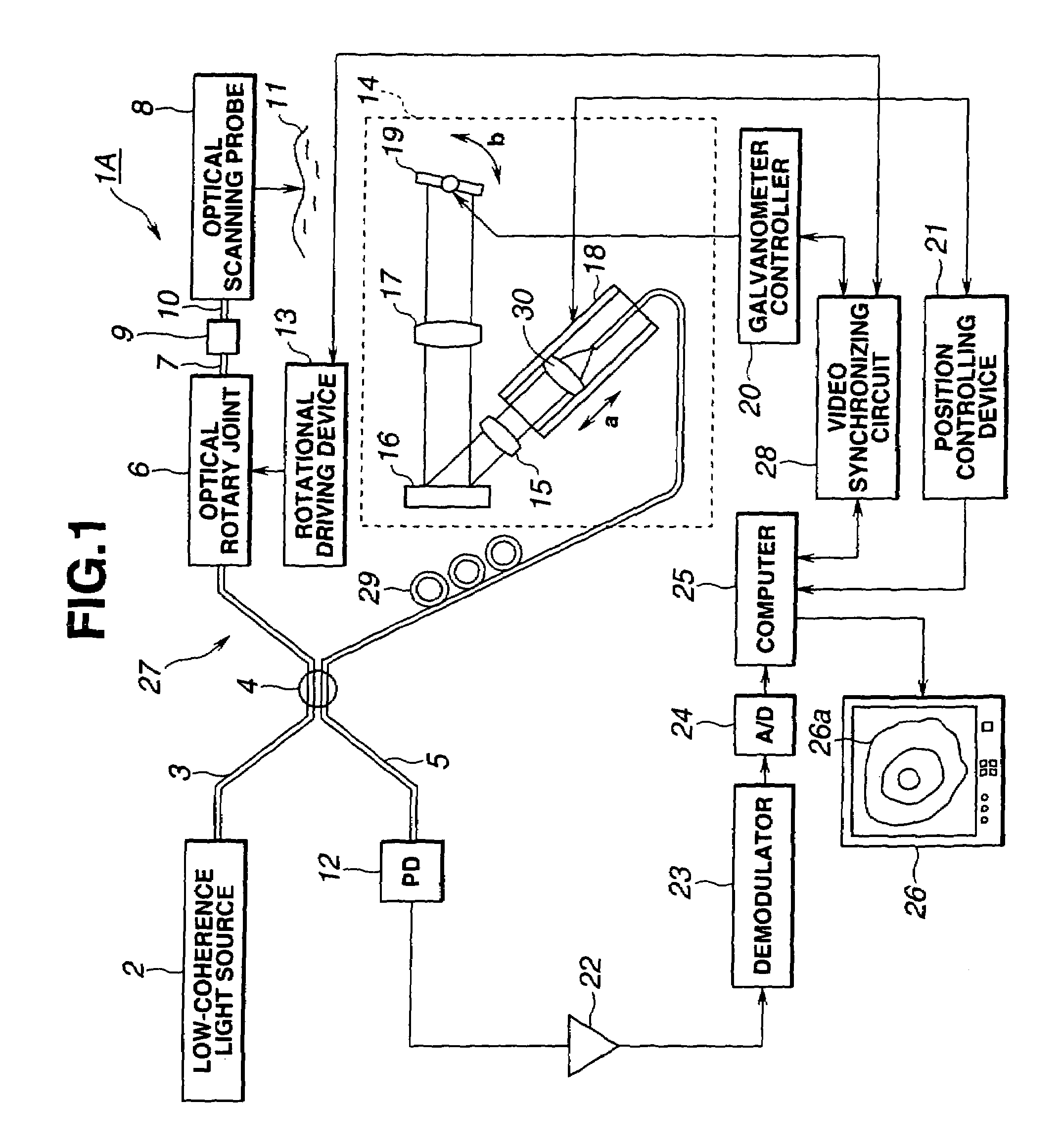
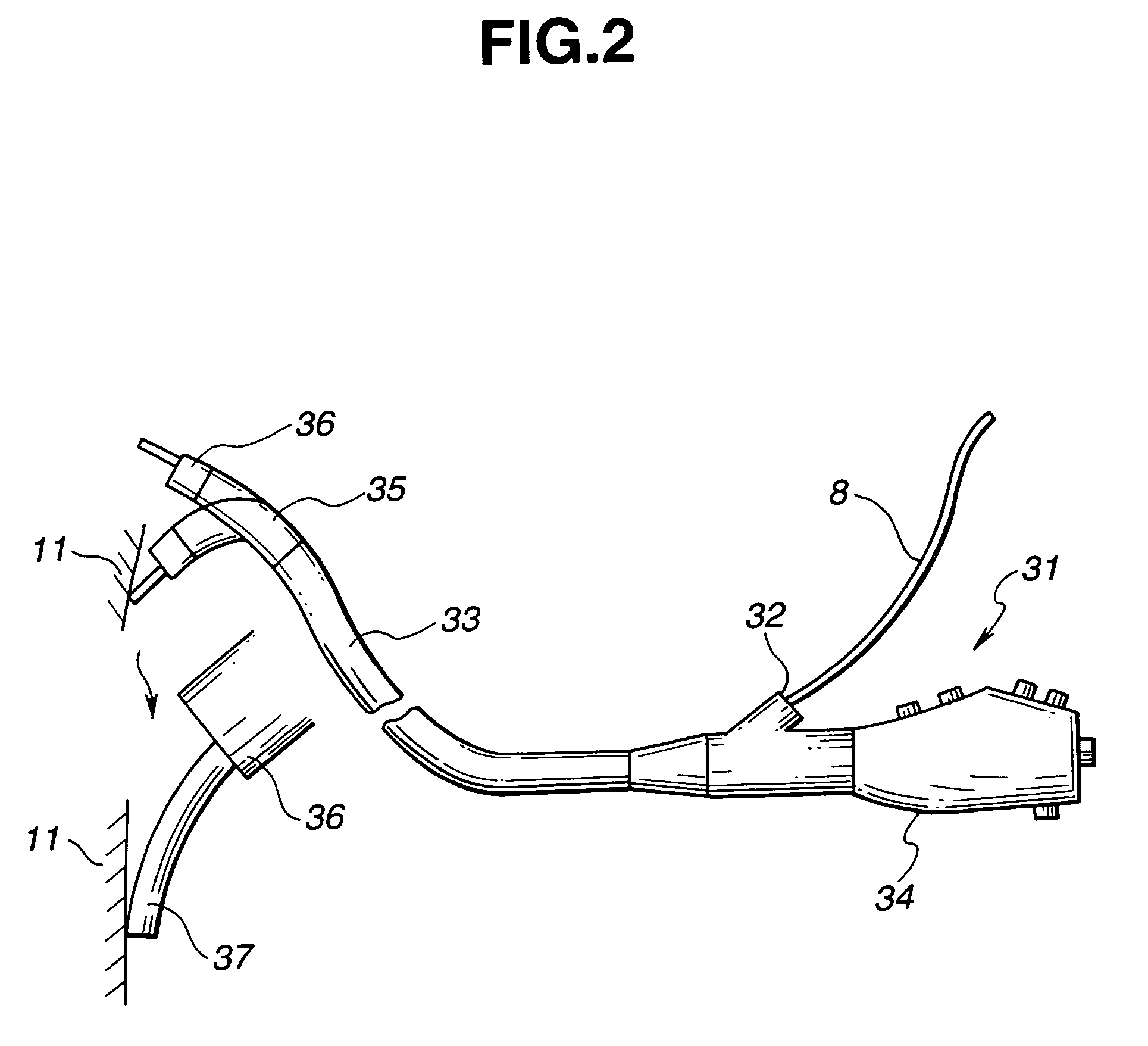
[0089]the present invention will now be described with reference to FIG. 1 through FIG. 7B.
[0090]An object of the present embodiment is to prevent shifting of the shafts, inclination in the angle, and slack in the shaft direction from occurring between the rotating shaft of the rotation transmitting means provided to the optical scanning probe and the rotating shaft of the rotation driving means provided to the observation apparatus, and to secure a stable connection between the optical fiber of the optical probe and the optical fiber of the observation apparatus.
[0091]Also, another object is to secure a good optical connection by allowing the detachable single mode fiber provided to the connection portion of the observation apparatus and optical probe to be replaced without re-polishing even in the event that the fiber end at the observation apparatus side to be optically connected to the fiber end portion of the optical scanning probe is soiled.
[0092]Further, another object is to ...
second embodiment
[0167]Next, a second embodiment according to the present invention will be described with reference to FIGS. 8A and 8B.
[0168]The objects of the present embodiment are the same as those of the first embodiment.
[0169]The difference with the arrangement shown in FIG. 5 will be described below, and other configurations are the same as those of the first embodiment. A shaft retainer 103 is provided instead of the shaft retainer 68.
[0170]The ferrule 71 is connected to a ferrule retainer 104, with the connector housing 105 and ferrule retainer 104 being slidable in the horizontal direction (the axial direction of the single mode fiber 10), and the ferrule retainer 104 is pressed to the right by the elastic force of the spring 106.
[0171]The base side of the connector housing has a tapered portion 105a provided thereto, coming into contact with the curved portion 108 of a sliding member 107 formed of a sliding plastic such as Derlin, provided to the shaft retainer 103.
[0172]Contact is made b...
third embodiment
[0178]FIG. 9 shows the configuration of the connector connecting portion of the connector portion and rotation driving device according to the
[0179]The difference between the third embodiment shown in FIG. 9 and the first embodiment shown in FIG. 5 is that while with the first embodiment the optical adapter of the rotation driving device 13 rotates integrally with the rotating shaft 76, with the present embodiment, it is fixed.
[0180]With the present embodiment, the rotation transmitting pins 70 shown in FIG. 5 are not provided to the shaft retainer 111 provided instead of the shaft retainer 68 provided within the connector case 64 in FIG. 5.
[0181]Also, an optical fiber adapter 116 is provided in the inner hollow of the rotating shaft 115 provided instead of the rotating shaft 76 shown in FIG. 5. The tip end of this optical fiber adapter 116 comprises an optical adapter portion 117, with a ferrule 118 being provided to this optical adapter portion 117.
[0182]A ferrule 119 is provided ...
PUM
| Property | Measurement | Unit |
|---|---|---|
| coherency distance | aaaaa | aaaaa |
| coherency distance | aaaaa | aaaaa |
| distance | aaaaa | aaaaa |
Abstract
Description
Claims
Application Information
 - R&D
- Intellectual Property
- Life Sciences
- Materials
- Tech Scout
- Unparalleled Data Quality
- Higher Quality Content
- 60% Fewer Hallucinations
Browse by: Latest US Patents, China's latest patents, Technical Efficacy Thesaurus, Application Domain, Technology Topic, Popular Technical Reports.
© 2025 PatSnap. All rights reserved.Legal|Privacy policy|Modern Slavery Act Transparency Statement|Sitemap|About US| Contact US: help@patsnap.com


