
Heat exchanger system for circuit card assemblies

a heat exchanger and circuit card technology, applied in the direction of insulated conductors, power cables, cables, etc., can solve the problems of reducing the heat exchanger heat exchange performance, and expensive heat exchange elements, so as to reduce the cost, enhance the heat exchange effect, and simplify the construction

Active Publication Date: 2007-02-20
HARRIS CORP
View PDF10 Cites 34 Cited by
  • Summary
  • Abstract
  • Description
  • Claims
  • Application Information

AI Technical Summary

Benefits of technology

This solution provides efficient heat transfer with minimal pressure drop and increased structural rigidity, reducing maintenance needs and improving vibration performance, while allowing for the use of commercial off-the-shelf components.

Problems solved by technology

Initial efforts to meet VME bus specifications included chassis designs incorporating expensive and complex heat transfer elements.
While the system of the U.S. Pat. No. 5,835,349 patent provides a number of advantages over prior approaches, it nevertheless has some limitations.
This U-shaped flow path creates a relatively large pressure drop that reduces the heat transfer performance of the heat exchanger.
Additionally, the use of a gasket to seal the inlet and outlet of the heat exchanger reduces the reliability of the system, and creates a maintenance issue since the gaskets can be easily damaged and may require periodic replacement.

Method used


Image

  • Heat exchanger system for circuit card assemblies
  • Heat exchanger system for circuit card assemblies
  • Heat exchanger system for circuit card assemblies

Examples


Embodiment Construction

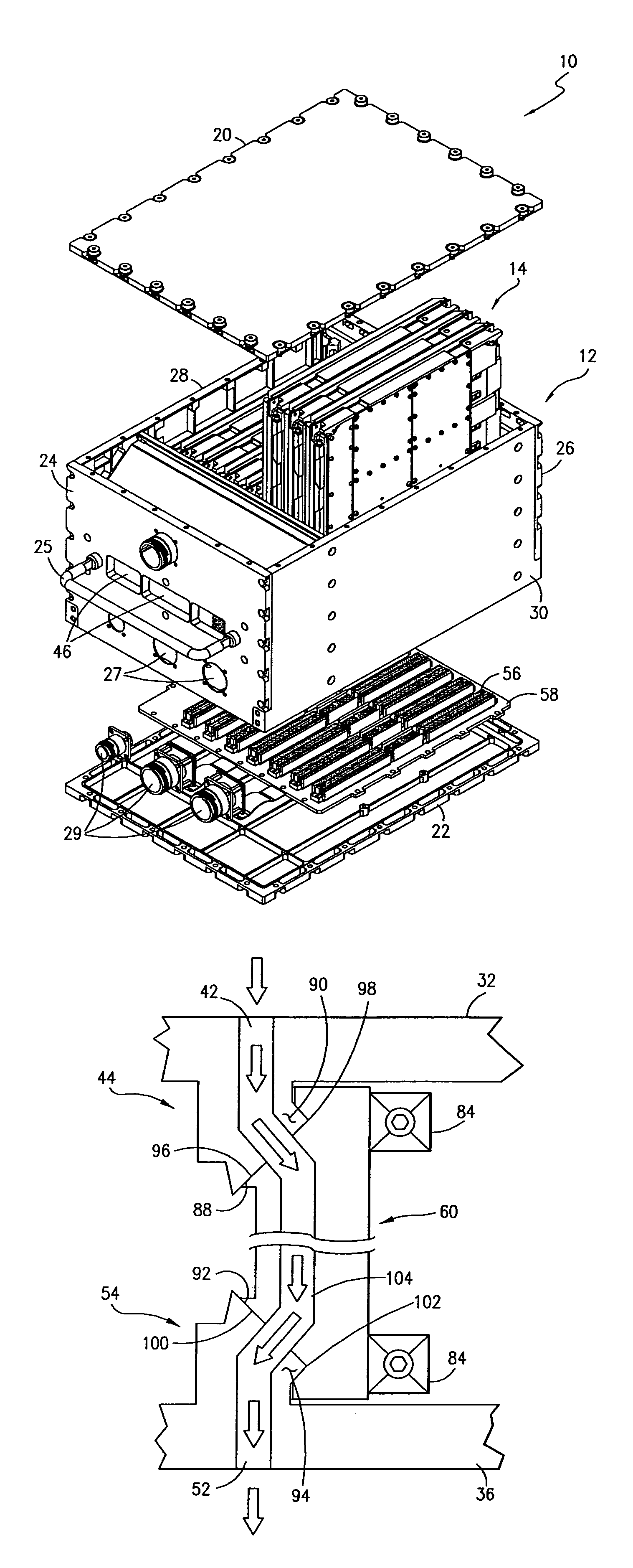
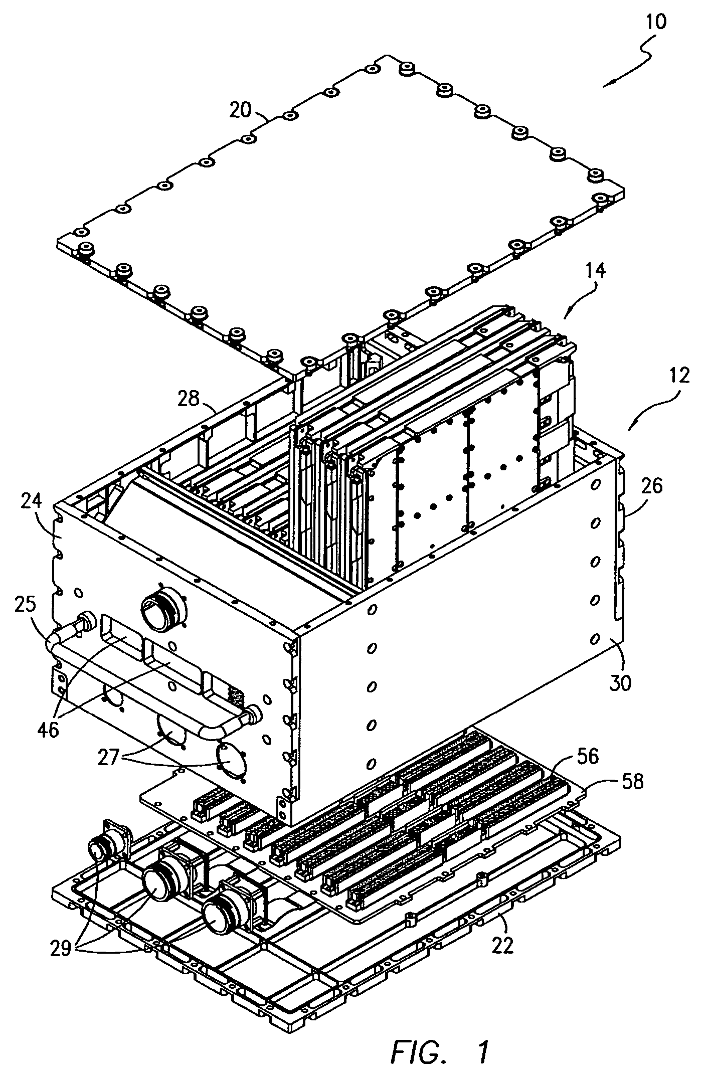
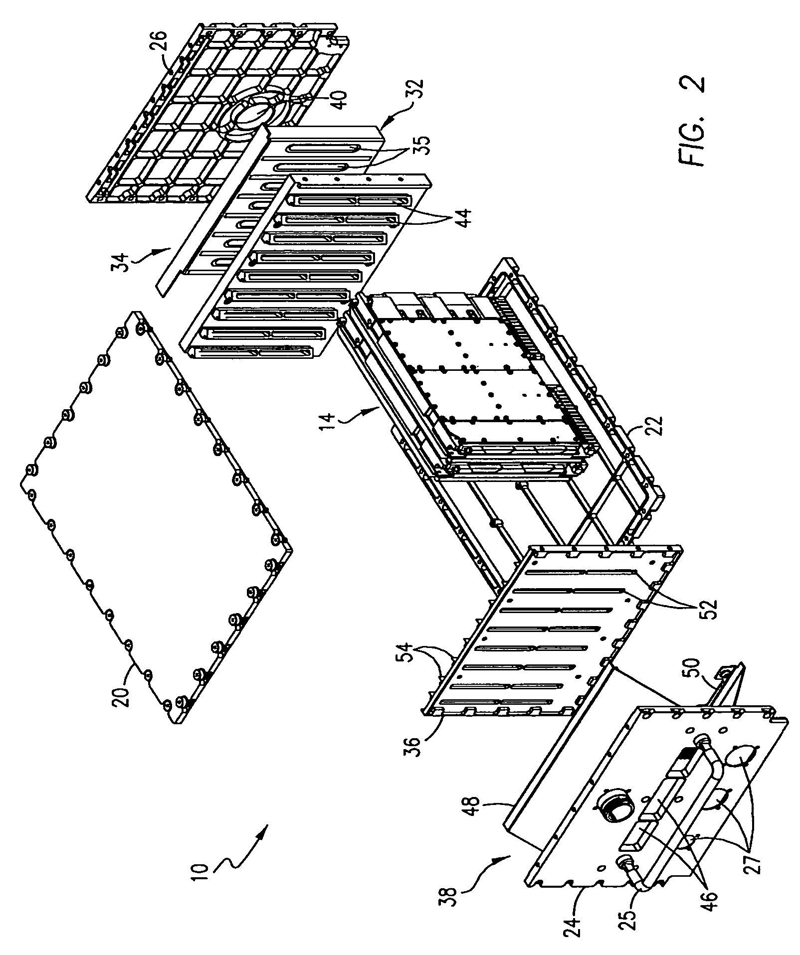
[0017]Referring now to the FIGS., the apparatus 10 of this invention includes a housing or chassis 12 having a hollow interior within which a number of modules 14 are mounted, each consisting of a straight-pass heat exchanger 16 directly connected to a circuit card assembly 18. The construction of the chassis 12 is described initially, followed by a discussion of the modules 14 and the connection between the two.

[0018]As best seen in FIGS. 1 and 2, the chassis 12 comprises a top wall 20, a bottom wall 22, a front wall 24, a back wall 26 and opposed side walls 28, 30 which are interconnected to form a hollow interior. The front wall 24 may be provided with a handle 25 and one or more apertures 27 to receive electrical connectors 29 as schematically depicted in the FIGS. An inlet end wall 32 is connected to the back wall 26 by an inlet plenum 34, and an outlet end wall 36 is mounted to an exhaust plenum 38 connected to the front wall 24. The back wall 26 is formed with an inlet port 4...


PUM


Abstract

An apparatus for housing and cooling circuit card assemblies employed in communication and other systems is disclosed including a chassis having opposed end walls which are formed with a series of spaced inlet card guides and correspondingly spaced outlet card guides, respectively. A straight-pass heat exchanger is directly mounted to each circuit card assembly via thermally conductive material, and opposed ends of the heat exchanger are mounted by a wedge lock to respective inlet and outlet card guides. The heat exchanger employs unique angled interface geometry that creates a gasketless airtight joint with complimentary inlet and outlet card guide geometry through which cooling air passes.

Description

FIELD OF THE INVENTION[0001]This invention is directed to an apparatus for mounting and cooling circuit card assemblies, and, more particularly, to a chassis including a number of self-sealing, straight-pass heat exchangers each directly mounted to a circuit card assembly forming a number of modules which are individually secured by wedge locks to an inlet card guide and an outlet card guide formed on opposed end walls of the chassis.BACKGROUND OF THE INVENTION[0002]Many communications systems, especially those intended for use in mobile platforms, must be environmentally robust both in terms of their hardware and signaling format. Airborne communication systems used with a plurality of UHF line-of-sight and satellite links, for example, may incorporate a transceiver mounting chassis or enclosure containing diverse communication equipment such as RF transmitter modules, RF receiver modules and various digital signal processing modules which control operation of the RF components and...

Claims


Application Information

Patent Timeline
Patent Type & Authority Patents(United States)
IPC IPC(8): H05K7/20
CPCH05K7/20563
Inventor STRAUB, JR., WALTER H.HOLMES, JONATHAN FRANKNGUYEN, VOI V.
Owner HARRIS CORP
Learn More