Adjustable clips

a technology of adjustable clips and clips, applied in the field of clips, can solve the problems of limited use range, easy separation under heavy loads, exposed hinge elements, etc., and achieve the effect of reducing manufacturing costs

Inactive Publication Date: 2007-02-27
FOLKMAR JAN
View PDF7 Cites 22 Cited by
  • Summary
  • Abstract
  • Description
  • Claims
  • Application Information

AI Technical Summary

Benefits of technology

[0013]In accordance with preferred aspects of the invention, the clip comprises only two parts that may each be molded as unitary items, thereby reducing manufacturing costs.
[0014]The adjustable hinge means comprises a pair of transversely spaced apart, axially aligned cheeks associated with one of said jaws; each of the cheeks has a generally vertically oriented elongated opening therein; a hinge pin unitarily formed with the other jaw is slidable along the opening. The opening is provided with a plurality of detents for arresting the sliding movement of the hinge pin, thereby permitting the spacing between the jaws at the hinge end of the clip to be adjusted as desired.

Problems solved by technology

Although clips of several different sizes are available, and a user will normally select a clip having an appropriate size, variations in the bag thickness for any given size of bag are such that they will have a limited range of use.
A further problem with bag clips, particularly of the larger sizes, is that the hinge elements are exposed to substantial levering forces, which tend to spring the hinge elements apart where these are of a type using a hinge pin, and skew the jaws.
Although this type of hinge is cost effective, it is prone to separating under heavy loads, due either to the use of cup and ball type bearings which engender a wedging apart of the cheeks under the influence of loading forces, or due to the channel walls being too easily deformed in a resilient manner.
However, this has heretofore prevented the snap engagement of the fixed hinge pin into the bearing openings, and it has been necessary to use a separately formed hinge pin, thereby increasing manufacturing costs, or to use a hook-together arrangement which reduces the integrity of the hinge.

Method used


Image

  • Adjustable clips
  • Adjustable clips
  • Adjustable clips

Examples


first embodiment

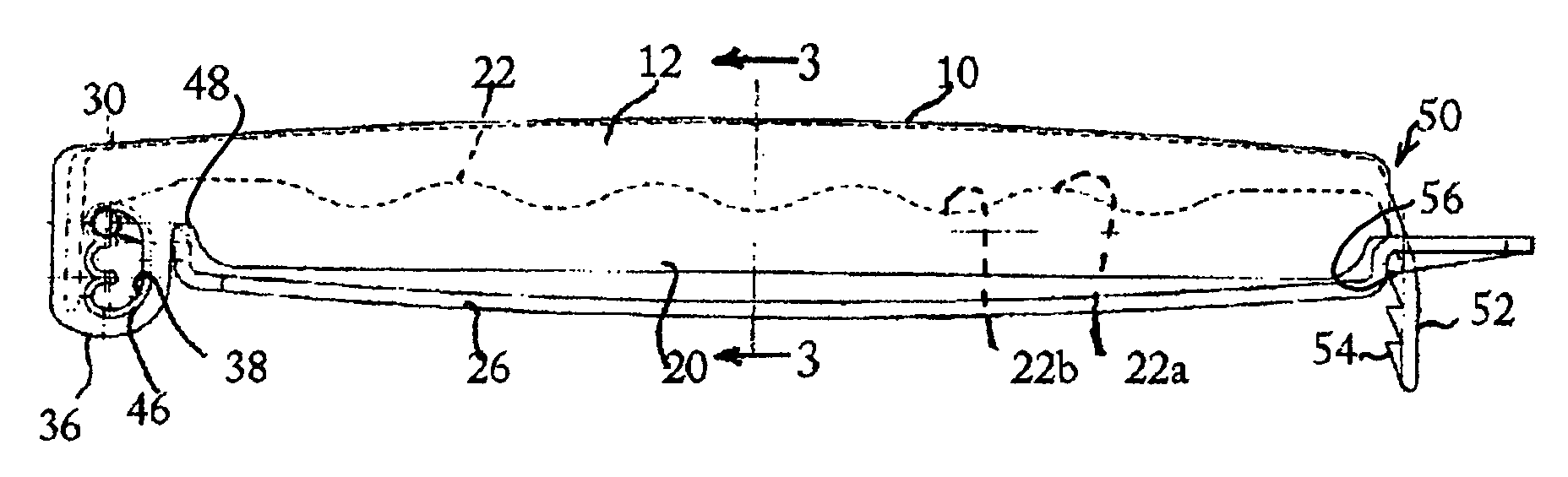
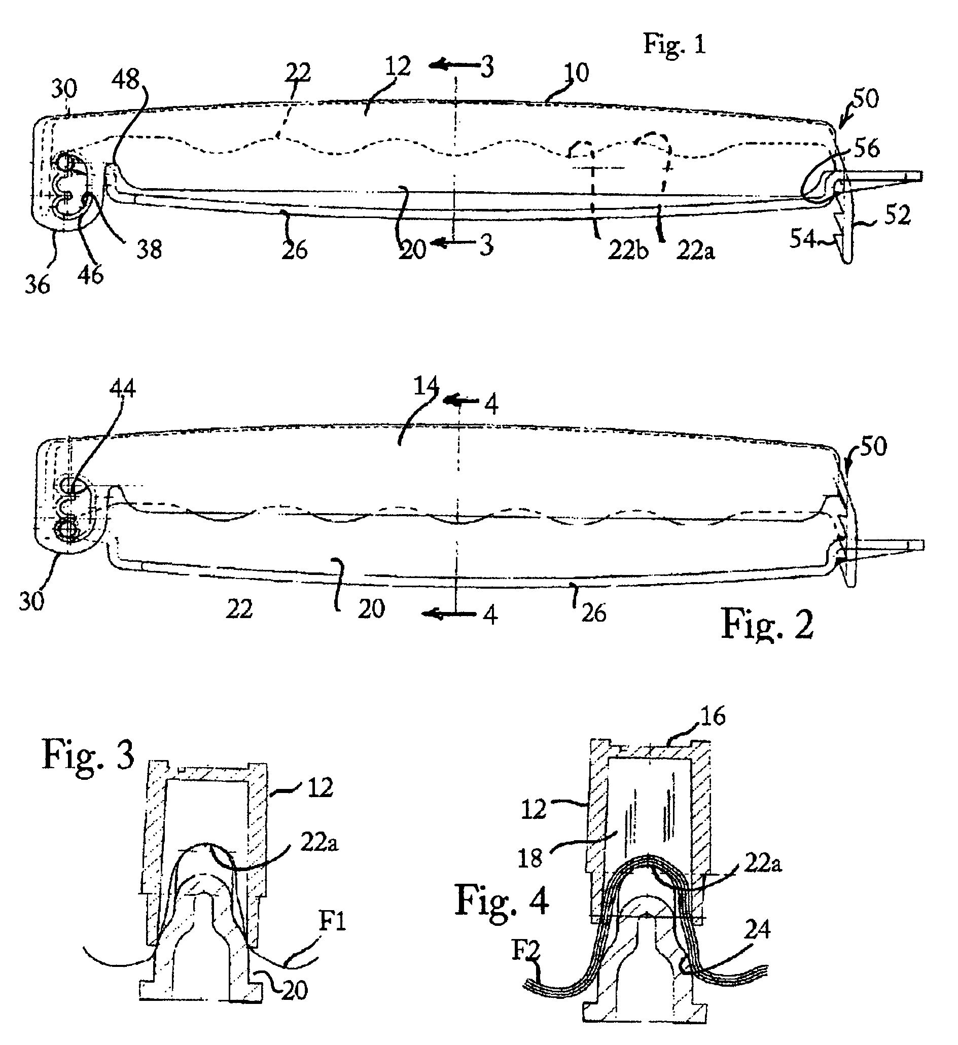
[0033]Referring to the drawings in detail, a clip in accordance with the invention is identified globally therein by the numeral 10. In the ensuing description, the terms upper, lower, forward, rearward and the like are used to facilitate the description of the drawing and are not to be construed as having an absolute meaning unless the context clearly indicates otherwise.

[0034]Clip 10 comprises an upper jaw 12, which includes side walls 14 joined along their length by a top wall 16 and at the rearward end by rear wall 18, to provide a relatively stiff, hollow beam structure. Clip 10 further comprises a lower jaw 20 having an upper surface 22 formed with an undulating profile to provide a plurality of crests 22a and troughs 22b therealong, with side shoulders 24 and a flange 26 extending substantially along the length thereof. As thus far described, clip 10 has elements in common with the clip described in the above referred to WO Patent document 02 / 076836, the contents of which are...

second embodiment

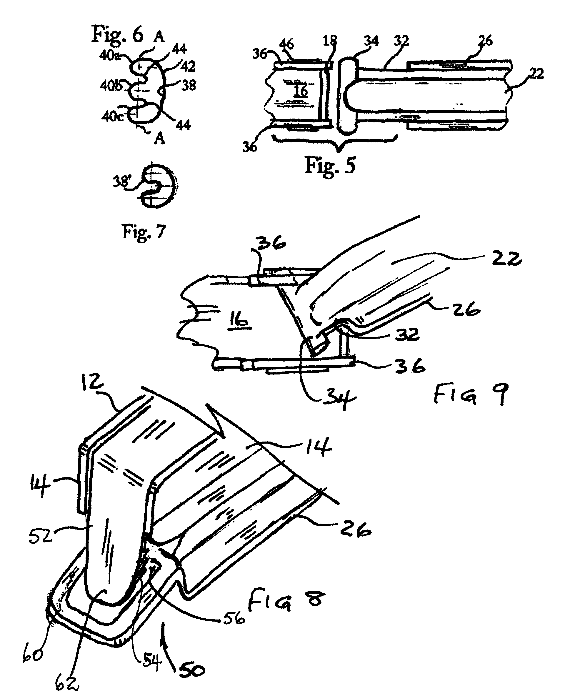
[0040]Considering now the invention, a clip at the hinge end thereof is identified by the numeral 110. It is to be understood that this clip may suitably be provided with a latch that is generally identical to the latch 50 of the clip 10 of the first embodiment. Clip 110 includes an upper jaw 112 and a lower jaw 120, and a hinge 130 about which the jaws may rotate between open and closed positions. Hinge 130 includes a hinge blade 132 which is associated with jaw 120, from which blade there projects a hinge pin 134 which is conveniently and preferably formed unitarily with the blade. Hinge pin 134 has a finger-like pawl tooth 135, which projects upwardly and rearwardly from the hinge pin.

[0041]Hinge 130 further comprises a pair of hinge cheeks 136, which are transversely spaced apart sufficiently to permit the passage of hinge blade 132 therebetween. Cheeks 136 each have a bearing opening 138 therein, which is vertically elongated. Opening 138 has a plurality of detents therein, in ...


PUM


Abstract

A plastic clip comprising two jaws united at one end by a hinge permitting them to swing between open and closed positions. The hinge may suitably be of the box type including a hinge blade associated with one jaw that is mounted between opposed cheeks associated with the other jaw by a hinge pin received in an elongated bearing opening in the cheeks, and along which the pin may travel to adjust the nip of the jaws. A spring latch at the opposite end of the jaws preferably permits a plurality of latching positions so as to permit the nip of the jaws at that end to be varied. The elongated bearing opening may permit the assembly of the jaws even where the box structure is relatively rigid and where the pin is integrally formed with the hinge blade.

Description

FIELD OF INVENTION[0001]This invention relates to clips, which may be used, for example, to releasably close storage bags.BACKGROUND OF THE INVENTION[0002]Clips in the general nature of those to which this invention relates are exemplified in patent documents WO 02 / 076836 and 99 / 19223, of common inventorship herewith. In general, such clips comprise a pair of axially elongated jaws which are hinged together adjacent one axial end thereof to permit them to swing between a closed position in which the jaws are mutually confronting substantially along their length, and an open position, and a latch disposed adjacent the opposed axial end for releasably retaining the jaws closed about a bag or the like as desired.[0003]The bags with which such clips may find use may vary considerably in their characteristics, for example from thin, single ply polymer film to thick, multi-ply paper. Although clips of several different sizes are available, and a user will normally select a clip having an ...

Claims


Application Information

Patent Timeline
Patent Type & Authority Patents(United States)
IPC IPC(8): B65D77/10B65D33/16
CPCB65D33/1675Y10T24/44299Y10T24/153Y10T24/44538Y10T24/15
Inventor FOLKMAR, JAN
Owner FOLKMAR JAN
Why Eureka
Try Eureka