Chemical vapor infiltration method for densifying porous substrates having a central passage

a technology of porous substrates and vapor infiltration methods, which is applied in the field of parts that have a central passage, can solve the problems of poor feeding of reactive gases, difficult process implementation, and high pressure in the center of the stack, and achieves the effect of high degree of densification

Inactive Publication Date: 2007-02-27
SAFRAN CERAMICS SA
View PDF14 Cites 31 Cited by
  • Summary
  • Abstract
  • Description
  • Claims
  • Application Information

AI Technical Summary

Benefits of technology

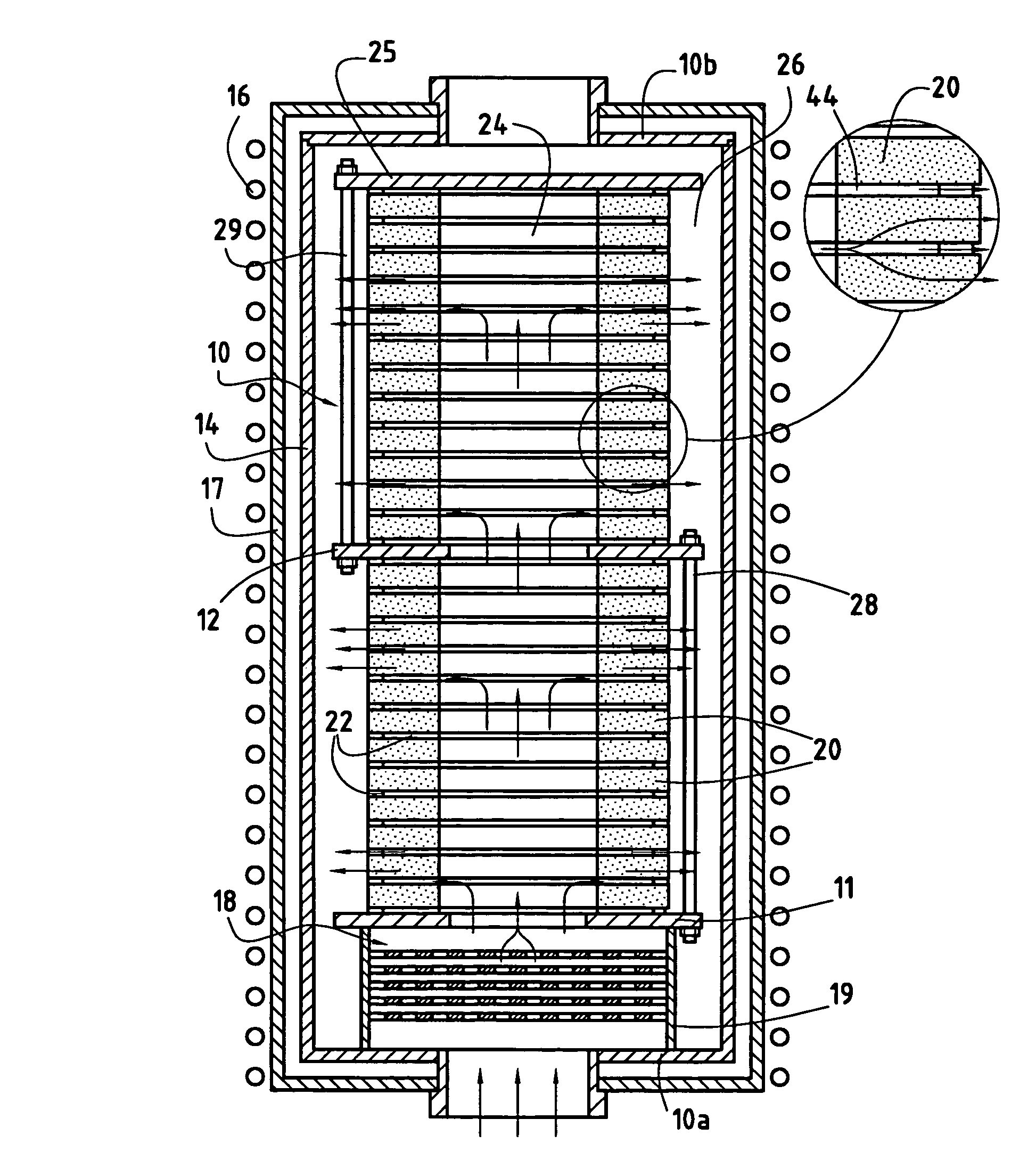
[0024]An object of the invention is to provide a method of using chemical vapor infiltration to densify porous substrates presenting a central passage, the method making it possible both to feed the substrates properly with reactive gas and to obtain a high degree of densification, more quickly than in the configurations described in above-mentioned U.S. Pat. No. 5,904,957, and without risk of the microstructure of the matrix material densifying the substrates becoming modified and without forming undesirable deposits.
[0034]The method of the invention is remarkable in that it makes it possible to combine the advantages of the above-mentioned directed flow and forced flow chemical vapor infiltration methods, while avoiding their drawbacks.
[0035]The pressure difference between the inside and outer volumes is capped, which makes it possible to avoid exceeding the pressure threshold beyond which modifications are likely to occur in the microstructure of the material constituting the matrix, or unwanted deposits are likely to occur, or beyond which swelling of the stack might become troublesome. The infiltration method can then be continued without difficulty until a relatively high level of densification is reached, which level can possibly even correspond to the desired final density for the densified substrates, such that there is then no longer any need for an additional infiltration step.

Problems solved by technology

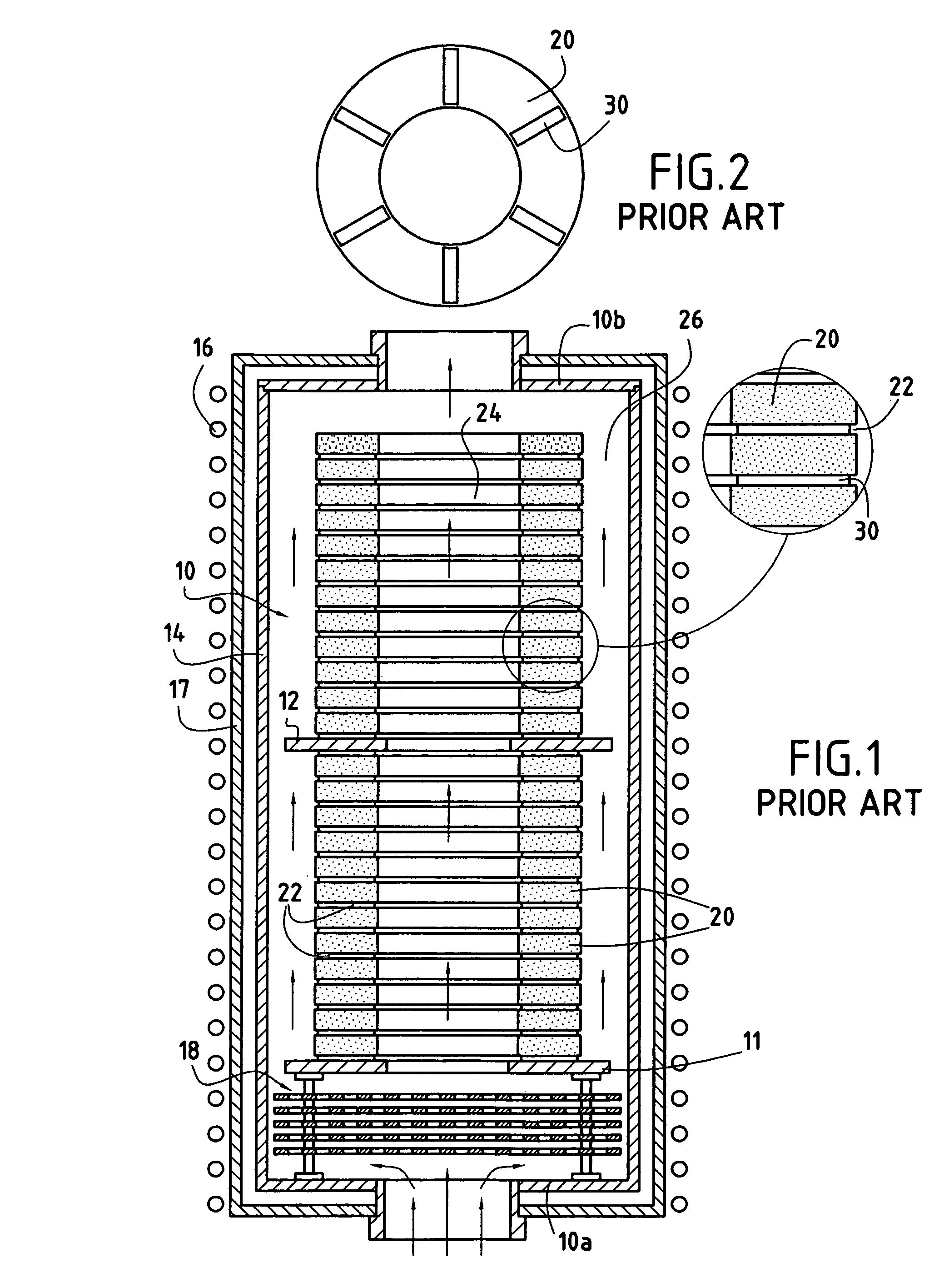
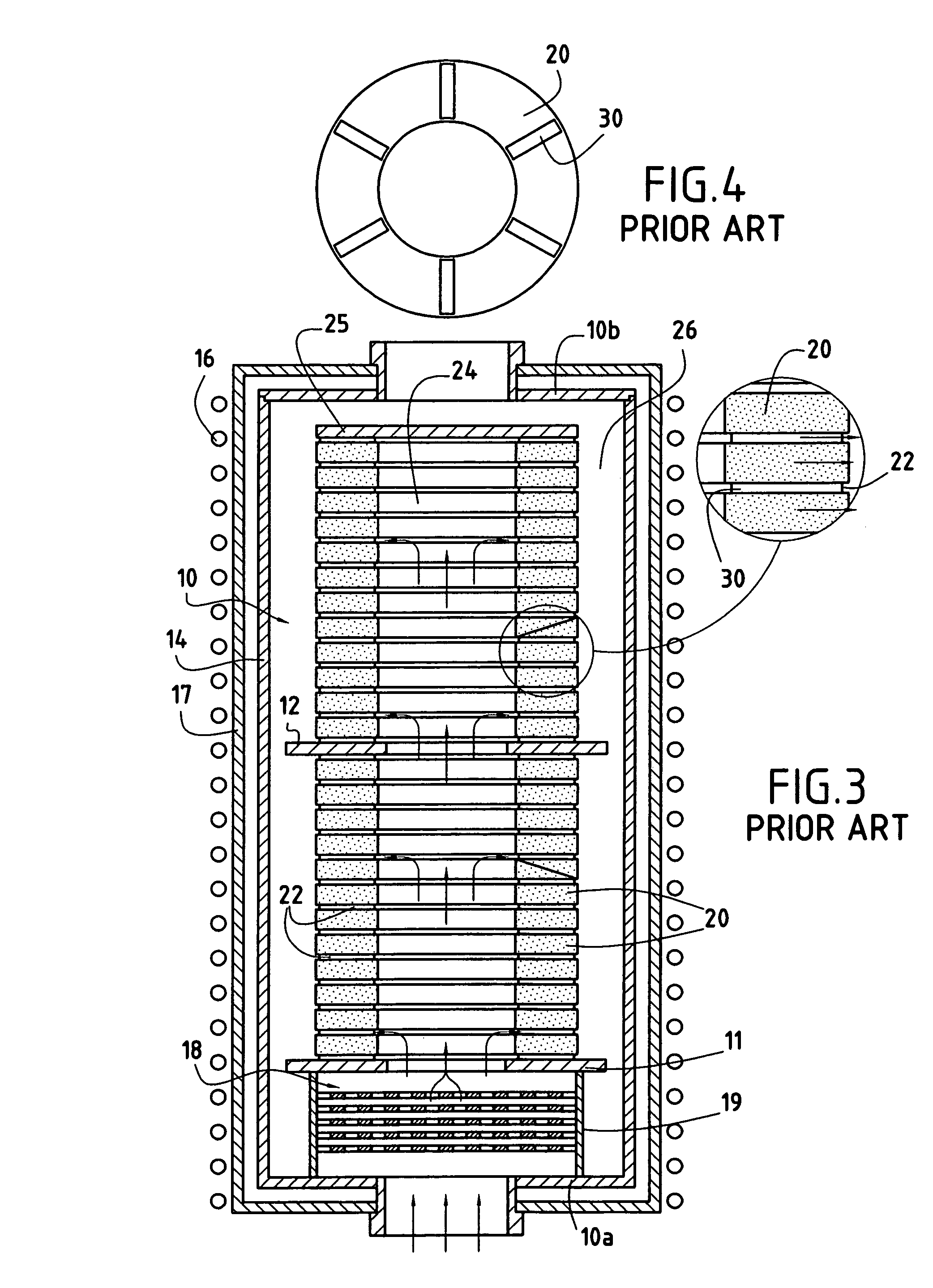
A drawback of such a disposition is that a relatively small fraction of the gas flows in the gaps 22, which means that the substrates 20 are poorly fed with reactive gas since their large faces are adjacent to the gaps 22.
However, the process is difficult to implement.
In addition, when the process is continued beyond a threshold of substrate densification, leading to the pressure in the center of the stack becoming too high, the microstructure of the matrix has been observed by the applicant to become modified, and indeed large quantities of soot can be formed.
Those phenomena are undesirable since they lead to a change in the properties of the material which can be harmful while it is in use.
In addition, the increase of pressure inside the stack as densification progresses causes the stack to swell, and that can have destructive effects.

Method used


Image

  • Chemical vapor infiltration method for densifying porous substrates having a central passage
  • Chemical vapor infiltration method for densifying porous substrates having a central passage
  • Chemical vapor infiltration method for densifying porous substrates having a central passage

Examples


example

[0102]An example of determining the total leakage section S is given below for a load of annular substrates constituting preforms for carbon brake disks.

[0103]The initial load was made up of 23 substrates stacked without any densification. Each substrate was constituted by a plurality of needled-together sheets of carbon fibers. Making preforms of this type for brake disks for use in aviation or in motor racing is well known. The substrates present an inside diameter of 26 centimeters (cm), an outside diameter of 48 cm, a height (thickness) of 3.6 cm, and a fiber volume fraction of 23% (percentage of the volume of the disks that is occupied by the fibers).

[0104]Initially, the pressure gradient between the inside and the outside of the stack was measured for different admitted gas flow rates, using annular spacers that were solid so as to leave no leakage passage (S=0), i.e. in a situation of forced-flow infiltration as described in above-mentioned document EP 0 792 385. Measurement ...


PUM

PropertyMeasurementUnit
volume fractionaaaaaaaaaa
thicknessaaaaaaaaaa
diameteraaaaaaaaaa

Abstract

Annular substrates (20) are stacked in an enclosure where they define an inside volume (24) and an outer volume (26) outside the stack. A gas containing at least one precursor of a matrix material to be deposited within the pores of the substrates is channeled inside the enclosure to a first one (24) of the two volumes, and a residual gas is extracted from the enclosure from the other one (26) of the volumes. One or more leakage passages (22) allow the volumes to communicate with each other, other than through the substrates. The total section of the leakage passages has a value lying between a minimum value for ensuring that a maximum gas pressure in the first volume is not exceeded until the end of densification, and a maximum value such that a pressure difference is indeed established between the two volumes from the beginning of densification.

Description

BACKGROUND OF THE INVENTION[0001]The invention relates to making parts out of composite material comprising a porous substrate densified by a matrix, and it relates more particularly to making parts that have a central passage.[0002]The invention is particularly, but not exclusively, applicable to making annular brake disks or diverging portions or throats for rocket engine nozzles out of thermostructural composite materials.[0003]Thermostructural composite materials are remarkable for their high mechanical properties and their ability to retain these properties at high temperature. Typical examples of thermostructural composite materials are carbon-carbon (C—C) composites comprising a porous reinforcing substrate of carbon fibers densified by a matrix of carbon, and ceramic matrix composites (CMCs) comprising a porous reinforcing substrate of refractory fibers (e.g. carbon fibers or ceramic fibers) densified by a ceramic matrix (e.g. silicon carbide).[0004]Methods of densification ...

Claims


Application Information

Patent Timeline
Patent Type & Authority Patents(United States)
IPC IPC(8): C23C16/00C04B41/45B64C25/42C23C8/00C23C8/20C23C10/06C23C16/04C23C16/26C23C16/44C23C16/455F02K9/97
CPCC04B41/4531C23C8/00C23C8/20C23C16/45508C23C16/045C23C16/455C23C10/06
Inventor GOUJARD, STEPHANEBERNARD, BRUNORICHARD, JEAN-PHILIPPE
Owner SAFRAN CERAMICS SA
Why Eureka
Try Eureka