Image forming method

a technology of image forming and forming tubes, applied in the field of image forming methods, can solve the problems of difficult cleaning of the photoreceptor, inability to achieve high-quality images in practice, and use of small-diameter toners, etc., and achieve the effect of high-quality electrophotographics

Inactive Publication Date: 2007-02-27
KONICA MINOLTA INC
View PDF17 Cites 4 Cited by
  • Summary
  • Abstract
  • Description
  • Claims
  • Application Information

AI Technical Summary

Benefits of technology

[0084]The use of such a toner makes it possible to prepare toners having the above described particle size distribution, and to prepare toner particles which exhibit uniform surface properties of each particle, so that the effects of the invention are exhibited without degrading transferability.
[0085]The “salting-out / fusion”, as described above, refers to simultaneous occurrence of salting-out (aggregation of particles) and fusion (disappearance of the boundary surface among particles) or an operation to render salting-out and fusion to occur simultaneously. In order to render salting-out and fusion to occur simultaneously, it is necessary to aggregate particles (resinous particles and colorant particles) at temperatures higher than or equal to the glass transition temperature (Tg) of resins constituting the resinous particles.<Releasing Agent>
[0086]The releasing agent employed for the purpose of the invention is not specifically limited. However, it is preferred that a crystalline ester compound (hereinafter named “specific ester compounds”) of the following formula (1) be used as the releasing agent:R1—(OCO—R2)n  General Formula (1)(R1 and R2 each represent a hydrocarbyl group having 1 to 0.40 carbon atoms, which may have a substituent and n is an integer from 1 to 4.)<Specific Ester Compounds>
[0087]In the general formula (1) of the specific ester compounds, R1 and R2 each represent hydrocarbyl group which may have a substituent.
[0088]The hydrocarbyl group R1 preferably has from 1 to 20 carbon atoms, more preferably from 2 to 5 carbon atoms.
[0089]The hydrocarbyl group R2 preferably has from 16 to 30 carbon atoms, more preferably from 18 to 26 carbon atoms.

Problems solved by technology

However, the intended high quality images are not obtainable in practice by using small diameter toner.
Rather, some problems result from the use of small diameter toner.
A problem in cleaning is one of them.
Since the apparent adhesive force of such small toner onto a photoreceptor increases, it is difficult to clean the photoreceptor.
Therefore, in the cleaning-process for cleaning the photoreceptor with a cleaning blade, toner particles remaining on the photoreceptor have a tendency to pass through between the photoreceptor and the edge of the cleaning blade to cause cleaning failure.
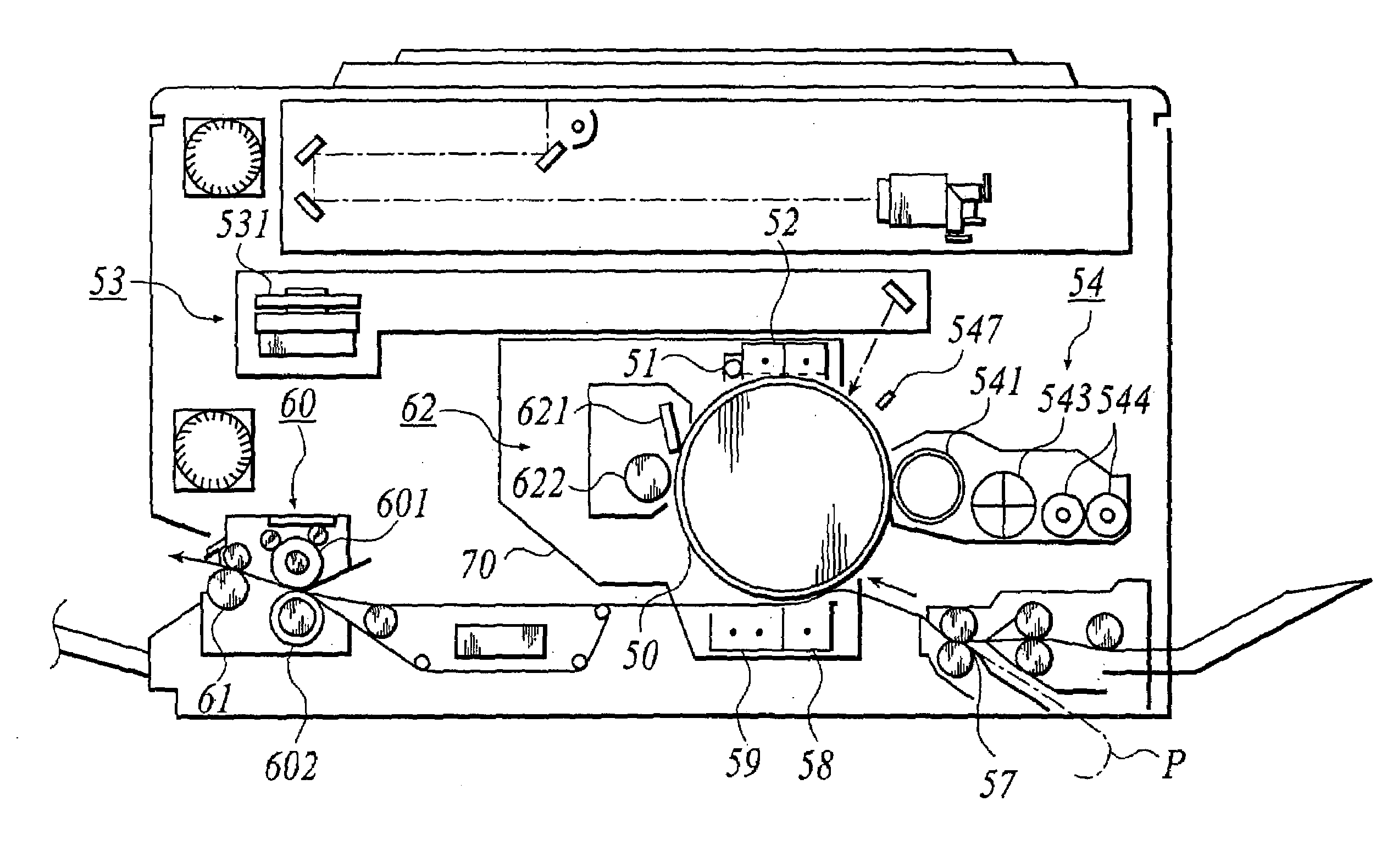
(1) A positional displacement between the photoreceptor and the exposing section causes a reduction of resolution due to a focal offset of a laser beam;
(2) A positional displacement between the photoreceptor and the developing section (Dsd) causes fogs, a reduction of the image density and a reduction of resolution;
(3) A positional displacement between the photoreceptor and the transfer section causes a reduction of the image quality such as thin spots and blurs of the transferred image; and
(4) A positional displacement between the photoreceptor and the cleaning blade involves a variation of the blade pressure, causing a cleaning failure and reduction of durability of the photoreceptor.
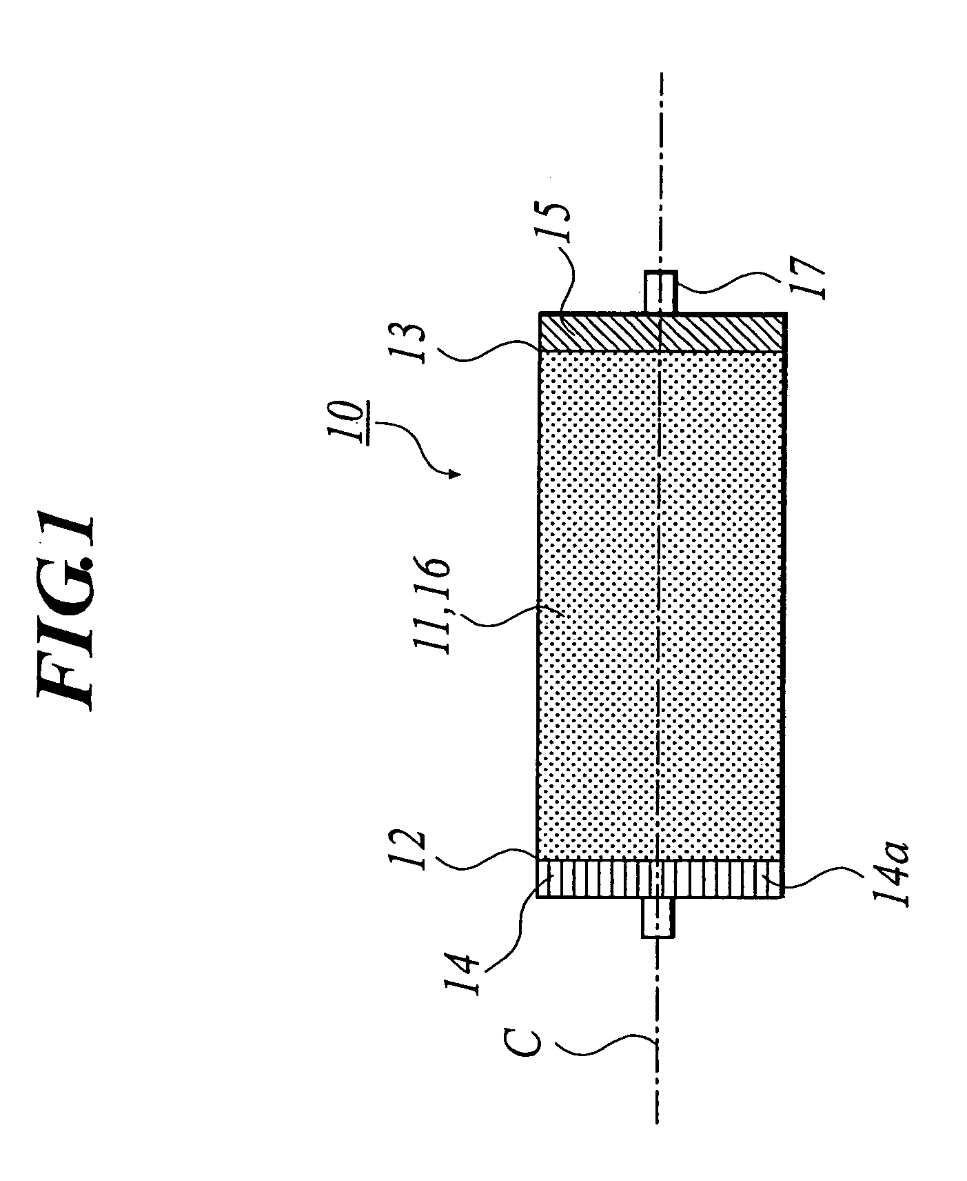
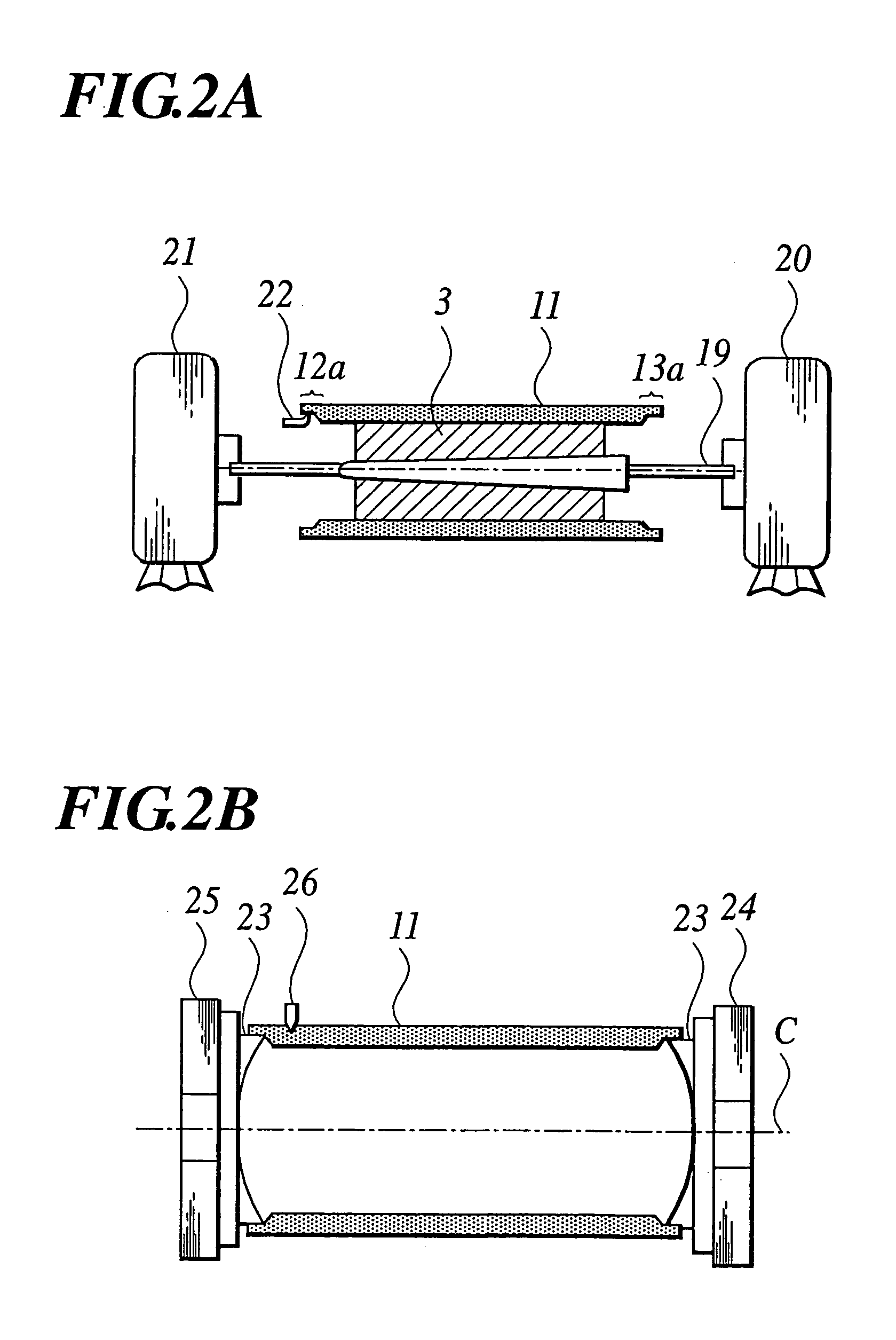
As described above, it will be understood that the above positional displacement between the photoreceptor and the image forming members around the photoreceptor significantly adversely affects the image quality of the electrophotographic image and also one of the factors for defining such positional relationship is positional accuracy of the photoreceptor.

Method used


Image

  • Image forming method
  • Image forming method
  • Image forming method

Examples


example 1

of Preparation of Latex

[0243]Into a 5,000 ml separable flask equipped with a stirrer, a temperature sensor, a cooling tube and a nitrogen gas feeder, a solution prepared by dissolving 7.08 g of an anionic surface active agent (sodium dodecylbenzenesulfonate: SDS) in 2,760 g of ion exchanged water was added. The inside temperature was raised to 80° C. under a nitrogen gas flow while stirring at 230 rpm. The compound represented by the aforementioned formula 19 (72.0 g) was added to a monomer mixture comprising 115.1 g of styrene, 42.0 g of n-butyl acrylate and 10.9 g of methacrylic acid. The mixture was then heated at 80° C. to dissolve the solids to obtain a monomer solution.

[0244]The heated monomer solution was mixed with and dispersed into the heated surface active agent solution using a mechanical type dispersing device provided with a circulation channel to obtain a dispersion containing emulsified particles having a uniform dispersion particle diameter. Subsequently, a solution...


PUM


Abstract

An image forming method having: developing a latent image formed on a cylindrical electrophotographic photoreceptor having a cylindricity of 5 to 40 μm, with a developer comprising a toner which comprises a ratio Dv50 / Dp50 of a 50% volume particle diameter Dv50 to a 50% number particle diameter Dp50 of 1.0 to 1.15, a ratio Dv75 / Dp75 of a cumulative 75% volume particle diameter from a largest volume particle diameter Dv75 to a cumulative 75% number particle diameter from a largest number particle diameter of Dp75 of 1.0 to 1.20, and toner particles having a particle diameter of 0.7×Dp50 or less in an amount of 10 percent by number or less.

Description

BACKGROUND[0001]1. Technical Field[0002]The invention relates to an image forming method for use in an electrophotographic copying machine or printer.[0003]2. Related Art[0004]In recent years, as a result of the modern progress of digital image processing techniques, digital image formation has become a mainstream of image forming methods. In the digital image forming method, basically, images comprised of minute dots of, for example, 400 dpi (dots per inch; the number of dots per 2.54 cm) are developed. Thus, high image quality techniques capable of faithfully reproducing such minute dot images are needed. Especially, in recent years, demands for compactness, higher resolution and full color image formation of copying machines and for improved resolution of printers have increased. In case higher accuracy such as high resolution is needed, further improved image quality techniques are also demanded.[0005]With a view toward realization of such high image quality, studies have been m...

Claims


Application Information

Patent Timeline
Patent Type & Authority Patents(United States)
IPC IPC(8): G03G13/01G03G5/04G03G5/043G03G5/047G03G5/10G03G9/08G03G15/06G03G15/08
CPCG03G5/04G03G5/043G03G5/047G03G15/08G03G9/0806G03G9/0819G03G5/10
Inventor TOMOYORI, KAGEYUKI
Owner KONICA MINOLTA INC
Why Eureka
Try Eureka