Piezoelectric/electrostrictive device

a technology of electro-electrostrictive device and thin diaphragm, which is applied in piezoelectric/electrostrictive/magneto-strictive device, piezoelectric/electrostriction/magneto-striction machine, etc., can solve the problems of difficult high-precision (high-sensitivity, high-resolution) detection, and achieve superior response and effective prevent the decay of the vibration of the thin diaphragm portion

Inactive Publication Date: 2007-02-27
NGK INSULATORS LTD
View PDF13 Cites 7 Cited by
  • Summary
  • Abstract
  • Description
  • Claims
  • Application Information

AI Technical Summary

Benefits of technology

[0009]The present invention has been developed in view of the above-described problems, and an object is to provide a piezoelectric / electrostrictive device which is superior in response and in which high-precision (high-resolution, high-sensitivity) detection is possible, while effectively preventing decay of vibration of a thin diaphragm portion and maintaining displacement (amplitude) to be high.
[0013]According to the present invention, there is provided the piezoelectric / electrostrictive device which effectively prevents the decay of the vibration of the thin diaphragm portion and which is superior in response while maintaining the displacement (amplitude) to be high and in which the high-precision (high-resolution, high-sensitivity) detection is possible.

Problems solved by technology

Moreover, since response is lowered, there is a problem that it is difficult to perform high-precision (high-resolution, high-sensitivity) detection.

Method used


Image

  • Piezoelectric/electrostrictive device
  • Piezoelectric/electrostrictive device

Examples


example 1

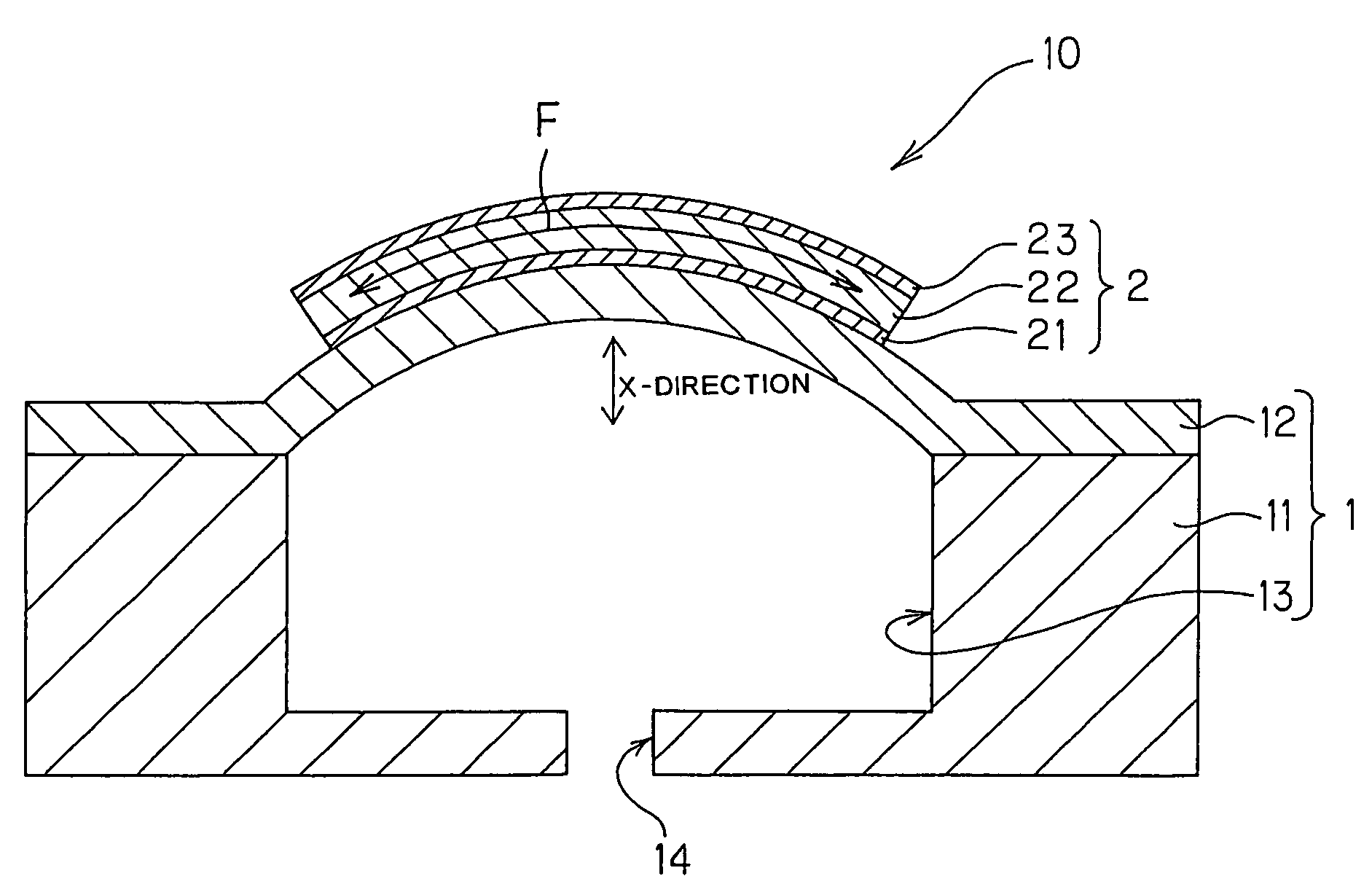
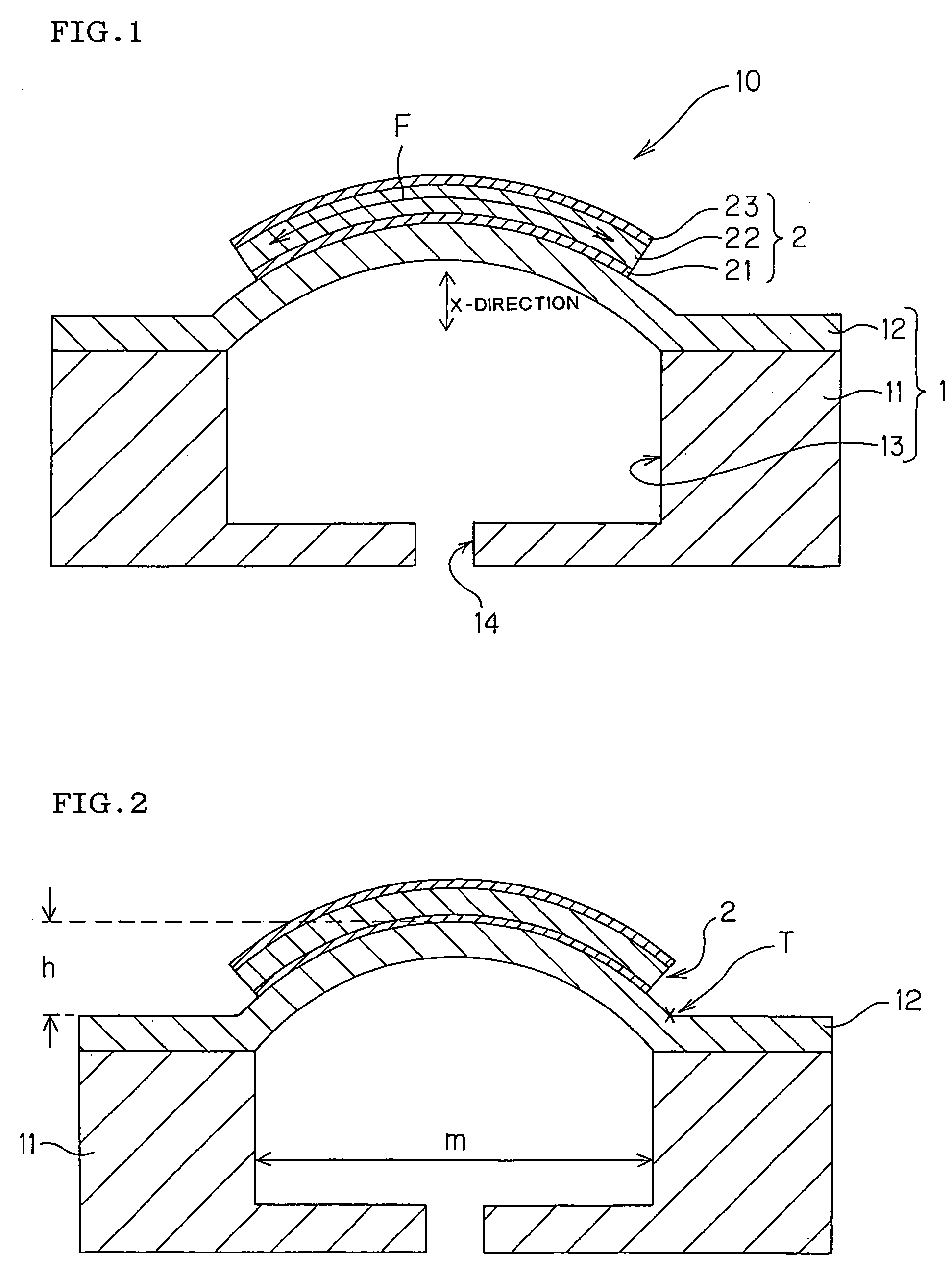
[0044]A ceramic substrate having an integral structure was prepared in which a frame-like thick portion having a rectangular cavity having a size of 6 mm×1.1 mm formed therein was covered by a thin diaphragm portion having a thickness of 10 μm. It is to be noted that the ceramic substrate was prepared by: mixing a ceramic mixed powder made of 80 wt % of a 3 mol % yttria partially stabilized zirconia powder and 20 wt % of an alumina powder and having an average particle diameter of 0.4 μm with a binder, a plasticizer, and an organic solvent by a usual method to prepare a slurry; molding a green sheet for the thick portion by use of the slurry in a doctor blade process in such a manner as to obtain a thickness of 200 μm after sintering; on the other hand, blending the 3 mol % yttria partially stabilized zirconia powder having an average particle diameter of 0.3 μm with the binder, the plasticizer, and the organic solvent by the usual method to prepare a slurry; thereafter molding a gr...

example 2

[0045]A piezoelectric / electrostrictive device was obtained in the same manner as in Example 1 except that a sintered body of a piezoelectric / electrostrictive material having a thickness of 20 μm and made of 0.98(Bi0.5Na0.5)TiO3-0.02KNbO3 (numerals being molar fractions) was separately sintered and obtained on a thin diaphragm portion of a ceramic substrate similar to that used in Example 1, and the sintered body was attached using a conductive adhesive while grasping the body with a jig to pull the body by a force corresponding to a tensile stress of 100 MPa.


PUM

PropertyMeasurementUnit
tensile stressaaaaaaaaaa
aspect ratioaaaaaaaaaa
thicknessaaaaaaaaaa

Abstract

A piezoelectric / electrostrictive device includes: a ceramic substrate having a frame-like thick portion, a thin diaphragm portion, and a cavity formed by the thick portion and the thin diaphragm portion to communicate with the outside; and a piezoelectric / electrostrictive element having a layered structure including a lower electrode, a piezoelectric / electrostrictive film, and an upper electrode. Furthermore, the thin diaphragm portion is provided with an outward protruding arch shape, and in the piezoelectric / electrostrictive element, there remains a tensile stress parallel to a fixed surface of the element to the thin diaphragm portion. The piezoelectric / electrostrictive device is superior in response, and in the device high-precision (high-resolution, high-sensitivity) detection is possible, while effectively preventing decay of vibration of a thin diaphragm portion and maintaining displacement (amplitude) to be high.

Description

BACKGROUND OF THE INVENTION[0001]1. Field of the Invention[0002]The present invention relates to a piezoelectric / electrostrictive device, more particularly to a piezoelectric / electrostrictive device for use as an actuator utilizing a flexural displacement, or various types of sensors (e.g., a sensor for a microphone, a viscosity sensor, etc.) for detecting fluid properties, sound pressure, micro weight, acceleration or the like.[0003]2. Description of the Related Art[0004]A piezoelectric / electrostrictive device is used as an actuator or various types of sensors. As such piezoelectric / electrostrictive device, there is disclosed, for example, a device for use in measuring fluid properties such as density, concentration, and viscosity (see Japanese Patent Application Laid-Open No. 8-201265). Such piezoelectric / electrostrictive device is used as a sensor by utilizing correlation between amplitude of the piezoelectric / electrostrictive device as a vibrator and viscous resistance of the fl...

Claims


Application Information

Patent Timeline
Patent Type & Authority Patents(United States)
IPC IPC(8): B41J2/045H01L41/09H01L41/187H01L41/22H01L41/313H01L41/314H02N2/00
CPCH01L41/098H10N30/2048
Inventor NANATAKI, TSUTOMUYOSHIOKA, KUNIHIKOYAMAGUCHI, HIROFUMI
Owner NGK INSULATORS LTD
Why Eureka
Try Eureka