Multiple flared antenna horn with enhanced aperture efficiency

a technology of aperture efficiency and antenna horn, which is applied in the direction of antennas, electrical equipment, etc., can solve the problems of significant cost savings, circuit modules constitute the most expensive parts of phased array systems, and not a practical approach in the design of antenna array, so as to facilitate the manufacture of antenna horns

Active Publication Date: 2007-02-27
NORTHROP GRUMMAN SYST CORP
View PDF26 Cites 207 Cited by
  • Summary
  • Abstract
  • Description
  • Claims
  • Application Information

AI Technical Summary

Benefits of technology

[0005]The present invention resides in an antenna horn element that exhibits very high aperture efficiency (typically over 90%). The horn structure of the invention is comprised of multiple flared sections, without any step discontinuities, which makes the horn structure very attractive from a manufacturing point of view. Briefly, and in general terms, the antenna horn of the invention comprises at least three contiguous flared horn sections. A first of the flared horn sections is adapted to be coupled to a waveguide and the last of the flared horn sections has an aperture through which electromagnetic energy is coupled to or from space. The slopes and lengths of the flared horn sections are selected to enhance desirable electromagnetic modes at the aperture, thereby enhancing the aperture efficiency and antenna gain.
[0007]In the disclosed embodiment of the invention, the desirable electromagnetic modes are TE modes and the flared horn sections are selected to enhance the TE modes and suppress any TM (transverse magnetic) modes at the aperture. Adjacent flared horn sections of the invention have slope discontinuities between them, but no step discontinuities. The lack of step discontinuities facilitates manufacture of the horn. Other aspects and advantages of the invention will become apparent from the following more detailed description, taken in conjunction with the accompanying drawings.

Problems solved by technology

These circuit modules constitute the most expensive parts of a phased array system, and minimizing the number of modules results in a significant cost savings.
This is not, however, a practical approach in the design of antenna array.
Increasing the aperture area results in increased weight and cost of the array.

Method used


Image

  • Multiple flared antenna horn with enhanced aperture efficiency
  • Multiple flared antenna horn with enhanced aperture efficiency
  • Multiple flared antenna horn with enhanced aperture efficiency

Examples


Embodiment Construction

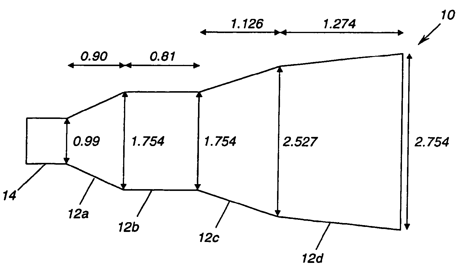
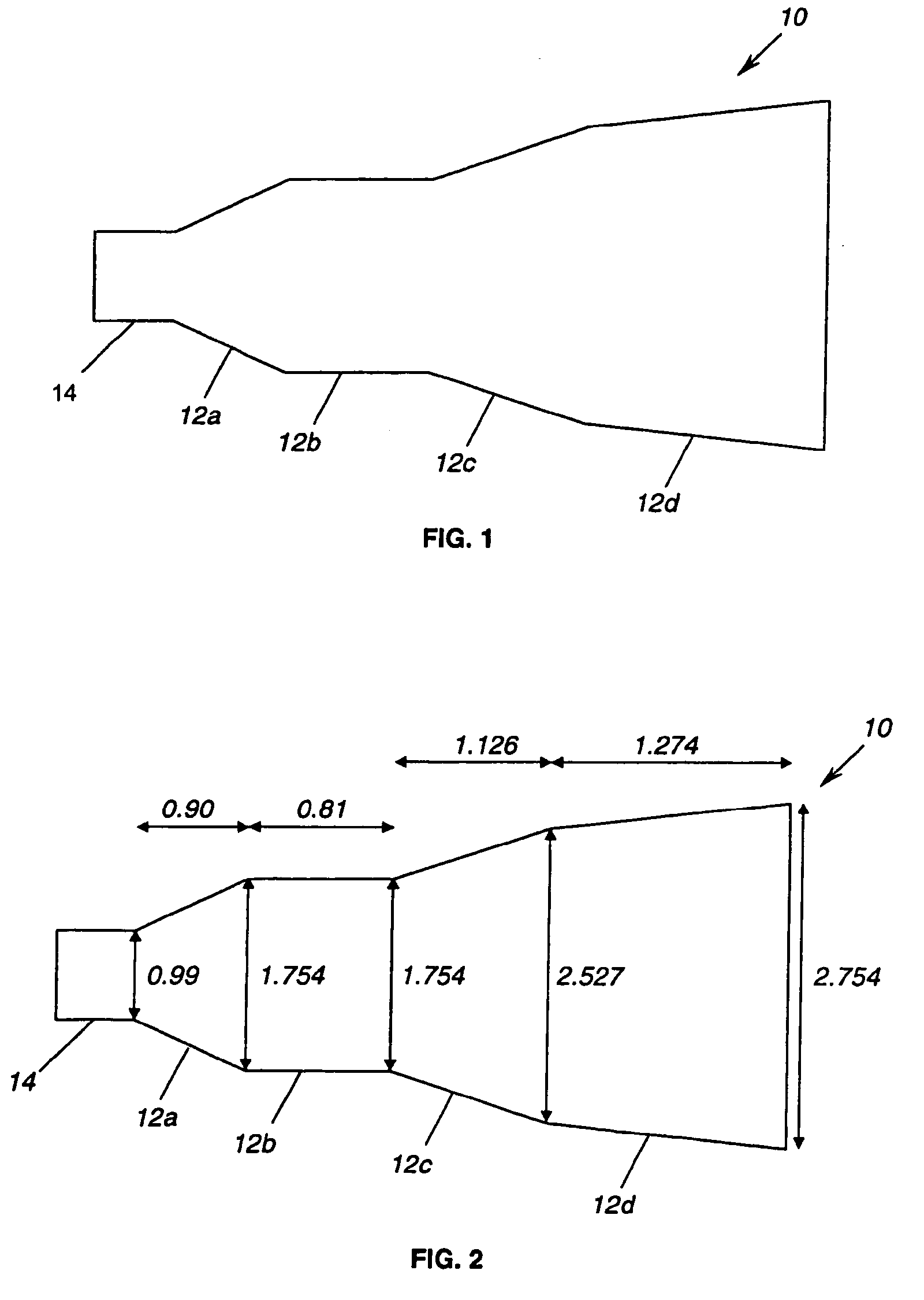
[0014]As shown in the drawings for purposes of illustration, the present invention is concerned with antenna horns and with techniques for improving the efficiency of antenna horns. The gain of an antenna is given by the expression:

[0015]G=4⁢π⁢⁢η⁢⁢Aλ2,

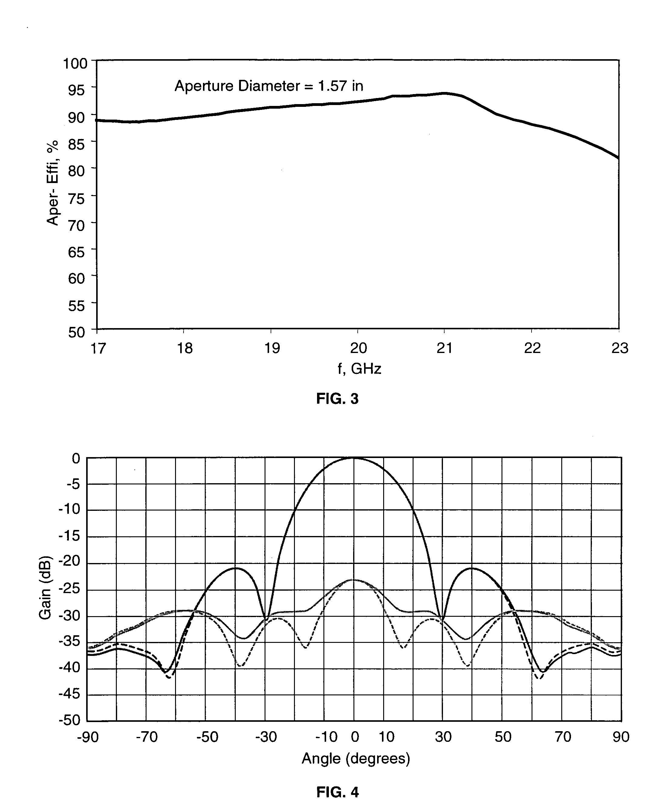
where G is the antenna gain, η is the aperture efficiency, A is the physical area of the aperture, and λ is the wavelength. Thus the antenna gain is directly proportional to the aperture efficiency.

[0016]In many applications, but particularly in the case of phased array antennas, it is highly desirable to provide an elemental antenna with an aperture efficiency as high as possible, because doing so increases the elemental gain and reduces the number of elements needed to form an array with a required overall gain. The present invention provides a new approach to improving the aperture efficiency of an antenna horn.

[0017]In accordance with the invention, an antenna horn includes multiple flared sections with flare angles and lengths sel...


PUM


Abstract

An antenna horn having multiple flared sections with their slopes and lengths selected to enhance desirable electromagnetic modes and to suppress undesirable modes at the horn aperture, thereby increasing the aperture efficiency and antenna gain.

Description

GOVERNMENT RIGHTS[0001]This invention was made with Government support under contract number F04701-02-C-0002 awarded by the Department of the Air Force. The Government has certain rights in this invention.BACKGROUND OF THE INVENTION[0002]This invention relates generally to antenna horns and, more particularly, to antenna horns having multiple sections. Horn antennas are widely used in microwave communication systems. Basically a horn antenna is a flared structure that provides coupling between free space and a waveguide used to carry microwave signals, either received from the antenna or to be transmitted to the antenna. Although some microwave energy could be radiated from or received in an open-ended waveguide, flaring the open end of the waveguide results in better impedance matching between the waveguide and free-space. This flared horn antenna structure provides more efficient coupling both in transmit and receive modes. The efficiency of antenna horns is particularly importan...

Claims


Application Information

Patent Timeline
Patent Type & Authority Patents(United States)
IPC IPC(8): H01Q13/00
CPCH01Q13/025
Inventor BHATTACHARYYA, ARUN K.SOR, JAMES
Owner NORTHROP GRUMMAN SYST CORP
Why Eureka
Try Eureka