Eureka AIR delivers breakthrough ideas for toughest innovation challenges, trusted by R&D personnel around the world.

Magnetic hard disk drive

a magnetic hard disk and magnetic technology, applied in the field of information storage systems, can solve the problems of data in the data area, head may not accurately detect the occurrence of positional displacement, and already moved well into the undetectable, so as to enhance the reliability of the disk, increase the density of data tracks, and improve the shock resistance performance during operation.

Inactive Publication Date: 2007-02-27
HITACHI GLOBAL STORAGE TECH JAPAN LTD
View PDF19 Cites 1 Cited by
  • Summary
  • Abstract
  • Description
  • Claims
  • Application Information

AI Technical Summary

Benefits of technology

[0011]The number of servo areas per circumference of a disk may be increased in order to reduce the interval at which the head position is detected (thereby decreasing the time it takes to detect a position fault). However, the size of the data areas will undesirably decrease with the number of servo areas increases.
[0013]For at least the reasons described above, the function of detecting the positional displacement of the head of a conventional magnetic hard disk drive does not have the desired accuracy such that the recording operation can be reliably aborted upon the occurrence of positional displacement. Under such circumstances, particularly for a magnetic hard disk drive with an increased data track density, a need may exist to provide a technology in which the shock resistance performance during operation is improved by preventing the fatal error of overwriting of the adjacent tracks to enhance the reliability of the disk.
[0014]In a magnetic hard disk drive according to at least one preferred embodiment of the present invention, an area in which track position information having a smaller data size than that of the recorded servo information is provided immediately at the front of each sector block in order to address one or more of the foregoing limitations of the conventional magnetic disks. In the present invention, the area in which track position information having a smaller data size than that of servo information is recorded is referred to as a “micro-servo area.” The track position information preferably has a smaller data size than that of the servo information so as not to require a compression in the data area.

Problems solved by technology

Accordingly, even if a positional displacement of the head occurs between servo areas, the head may not accurately detect the occurrence of the positional displacement thereof.
However, the head has already moved well into the undetectable section, and the data in the data area (sector block #4) of the adjacent track (#3) has been overwritten and corrupted.
In the state of FIG. 9(c), even if the data can be normally reproduced, a user may not be able to distinguish which data is the proper data written in final update.

Method used


Image

  • Magnetic hard disk drive
  • Magnetic hard disk drive
  • Magnetic hard disk drive

Examples


first exemplary embodiment

[First Exemplary Embodiment]

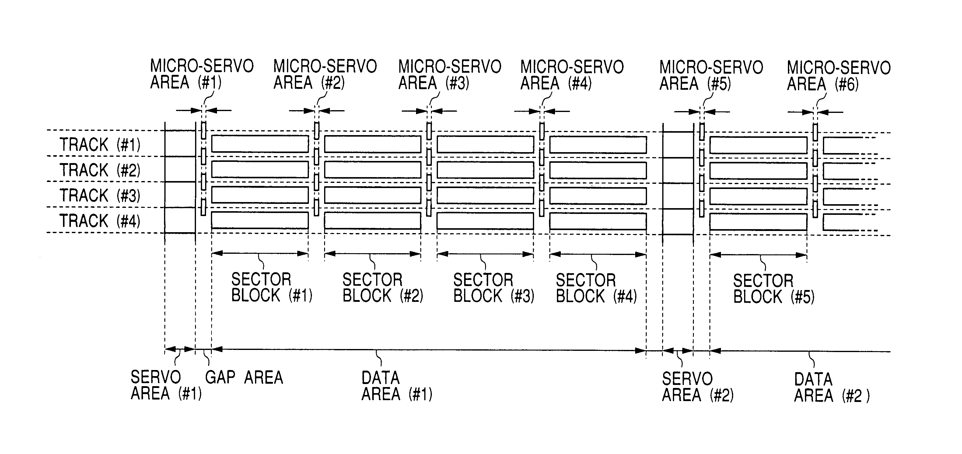
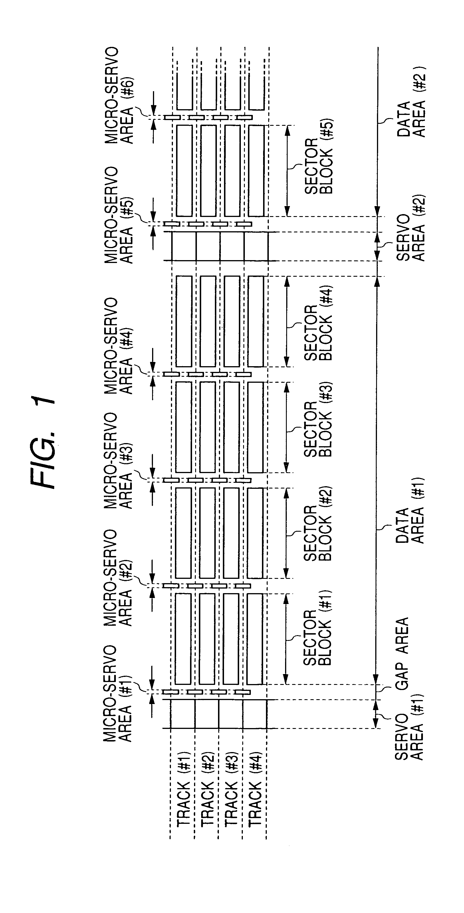
[0034]FIG. 1 shows an example of a configuration of micro-servo areas according to at least one preferred embodiment of the present invention. The crosswise direction of the diagram corresponds to the direction around the circumference of a disk, and the vertical direction of the diagram corresponds to the radial direction of the disk. A head is fixed on a rotary actuator, while the disk is rotating at a speed of from approximately 6 to 50 m / sec from the right to the left of the diagram. This state is relatively identical to the state in which the head is moving over the disk from left to right of the diagram. Since this description is easier to understand, the following description describes the head moving over the disk, but the typical case of the disk moving underneath the head is also assumed.

[0035]FIG. 1 shows the configuration of a section covering 4 tracks, from track (#1) to track (#4), in each of which a data area (#1) is placed between a servo ...

second exemplary embodiment

[Second Exemplary Embodiment]

[0054]FIG. 4 is a flowchart for illustrating the process of controlling the execution of the read and write operations to the data block by using the micro-servo area of the present invention. In Step 1, a determination is made as to whether the host side request is a read instruction or a write instruction. If the request is a read instruction, the, process preferably skips Step 5 where the read instruction is executed. Thereafter, the process shifts to the procedure of normal termination.

[0055]If the request is a write instruction, the process advances to Step 2 where a controller waits for the detection of IDAM in the micro-servo area. The IDAM denotes the time to start the track check code included in the micro-servo area. When the detection of IDAM is confirmed, the detection of the track check code is subsequently performed in Step 3. In Step 4, a determination is made as to whether the detected track check code matches the code of the track to whi...

third exemplary embodiment

[Third Exemplary Embodiment]

[0062]FIG. 10 is a block diagram showing an example of a configuration of a circuit for detecting the track parity code from the micro-servo area of the present invention and for controlling a write gate signal. Initially, the reading of disk information will be described. The reproduced signal of the head is amplified by about 100 to 200 times by a head amplifier, and the amplified signal is then input into a data processing circuit having an equalizer and a decoder. In the example shown in FIG. 10, the circuit system preferably includes: a low pass filter (LPF); an auto gain controller (AGC); an analog / digital (A / D) converter; an equalizer; a decoder; a matched filter; an identification address mark (IDAM) detector; a temporary memory for a parity code; a comparator; a write gate (WG) controller; and an encoder. This circuit system generally provides the processing of the recorded / reproduced signals of the magnetic head, and it may also include other ci...


PUM

PropertyMeasurementUnit
speedaaaaaaaaaa
shock resistanceaaaaaaaaaa
widthaaaaaaaaaa

Abstract

A hard disk drive and magnetic medium including a servo area, a data area divided into a plurality of sector blocks and at least one micro-servo area disposed between two sector blocks. There may be a micro-servo area immediately preceding each of the plurality of sector blocks. The micro-servo areas include an address mark and a track parity check code that allow the detection of an external shock that causes the recording (write) head to skip to an adjacent track in the hard disk medium. The micro-servo area is smaller than the servo areas, and various numbers of different track parity check codes can be used for different resolution of shock detection. An acceleration sensor may also be provided to detect larger external shocks. By detecting various external shocks with improved accuracy, and aborting the recording operation of data if an external shock is detected, the corruption of data in adjacent tracks is substantially reduced to improve disk drive performance.

Description

CROSS-REFERENCE TO RELATED APPLICATIONS [0001]This application is a Continuation application of U.S. application Ser. No. 09 / 919,915 filed on Aug. 2, 2001 now U.S. Pat. No. 6,822,818. Priority is claimed based on U.S. application Ser. No. 09 / 919,915 filed on Aug. 2, 2001, which claims priority of Japanese Patent Application 2000-357616 filed on Nov. 20, 2000.BACKGROUND OF THE INVENTION[0002]1. Field of the Invention[0003]The present invention relates to an information storage system including a magnetic head and a magnetic recording medium and, more particularly, relates to a portable magnetic hard disk drive having an improved shock resistance performance particularly during operation.[0004]2. Description of the Background[0005]The magnetic hard disk used in current magnetic hard disk drives typically includes a structure in which servo areas and data areas divided into a plurality of sector blocks are formed on concentrically formed tracks as shown in FIG. 6. In each of the servo ...

Claims


Application Information

Patent Timeline
Patent Type & Authority Patents(United States)
IPC IPC(8): G11B15/04G11B19/04G11B5/012G11B5/55G11B5/596G11B20/10G11B20/12G11B21/10G11B27/30
CPCG11B5/012G11B5/5582G11B5/59611G11B20/10G11B20/1252G11B27/3027G11B2220/2516G11B2020/1232G11B2020/1238G11B2020/1267G11B2020/1287G11B2220/20G11B5/59655G11B5/59694
Inventor HAMAGUCHI, TAKEHIKOAKAGI, KYOTAKANO, HISASHIICHIHARA, TAKAYUKI
Owner HITACHI GLOBAL STORAGE TECH JAPAN LTD
Why Eureka
Eureka Blog
Learn More