Motor manufacturing method

a manufacturing method and motor technology, applied in the manufacture of stator/rotor bodies, magnets, magnetic bodies, etc., to achieve the effect of reducing the length in the axial direction of the entire motor and reducing the length in the axial direction

Inactive Publication Date: 2007-03-06
AISIN AW CO LTD
View PDF14 Cites 14 Cited by
  • Summary
  • Abstract
  • Description
  • Claims
  • Application Information

AI Technical Summary

Benefits of technology

[0014]In this case, the unipolar coil is attached to the motor core by carrying out the axial positioning, and as a result, the protrusion dimensions at both ends protruding from both end surfaces in the axial direction of the motor core of the unipolar coil are aligned so as to be substantially the same. Accordingly, the lengths of the coil end portions protruding from both end surfaces of the motor core after being inserted become substantially un

Problems solved by technology

This problem occurs in the same manner even in the case that the motor core

Method used


Image

  • Motor manufacturing method
  • Motor manufacturing method
  • Motor manufacturing method

Examples


first embodiment

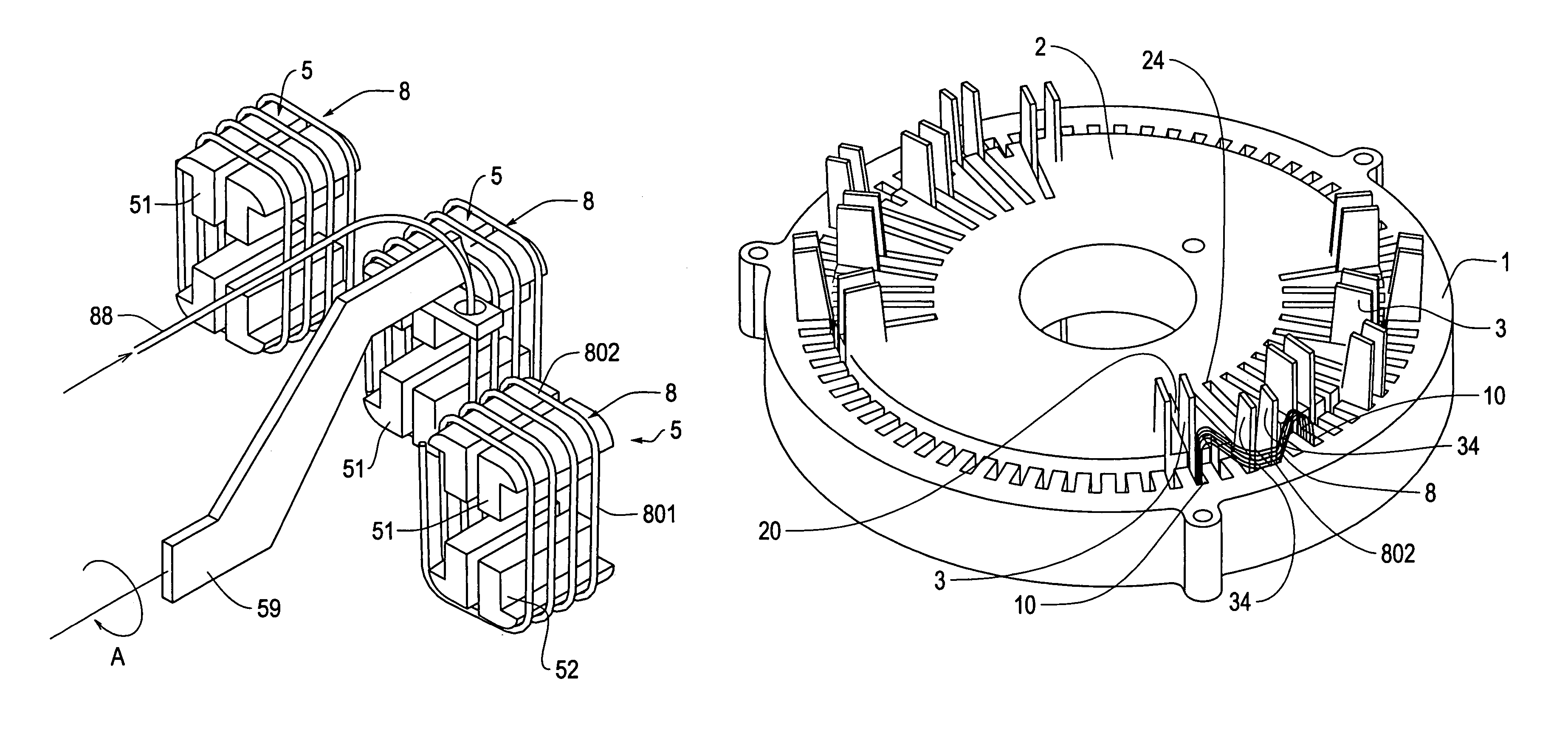
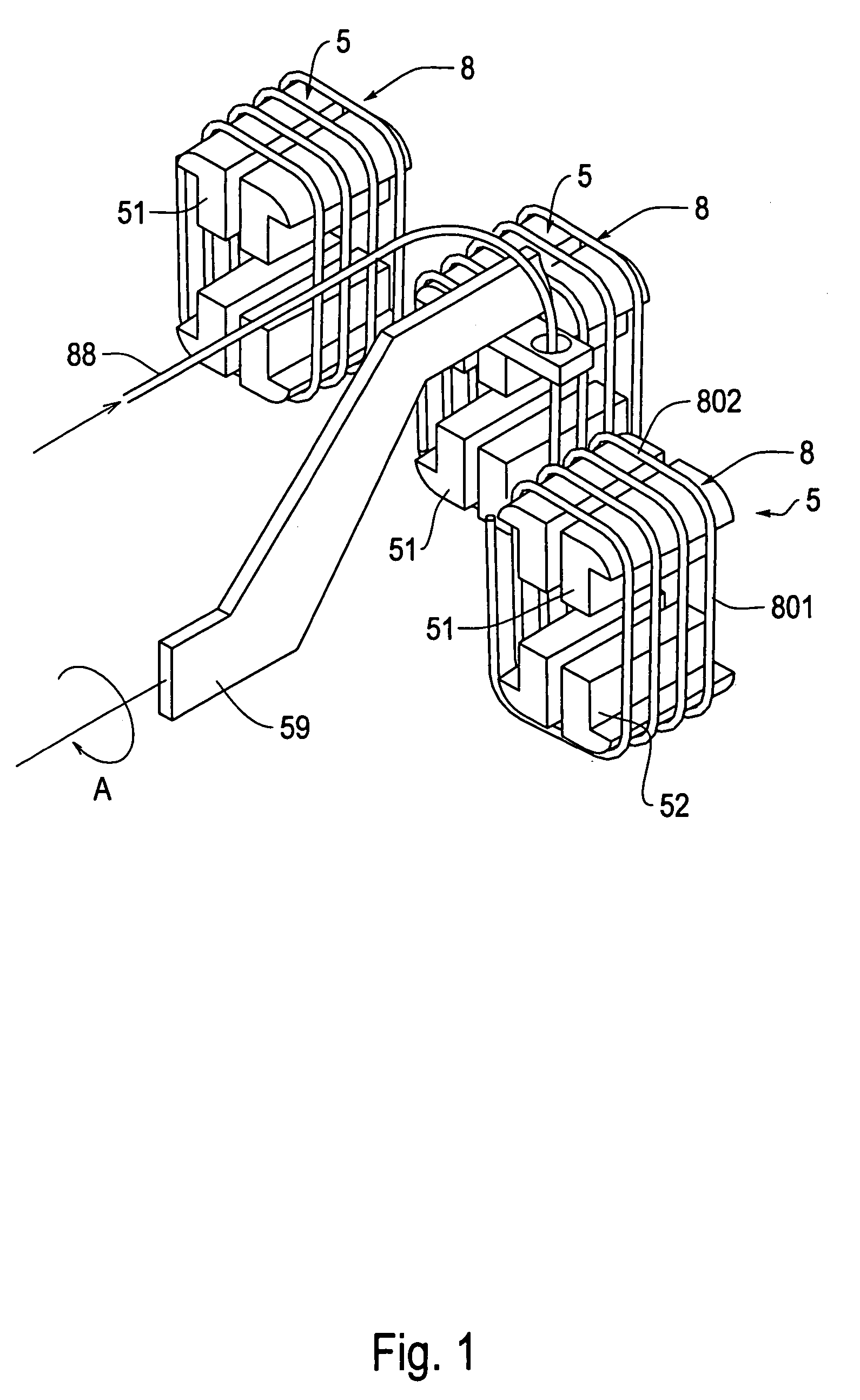
[0135]A significant point of this coil insertion apparatus 9 is that, as shown in FIG. 18, an angle of inclination α of the insertion blade 3 at a swing startup position with respect to the vertical direction is set within 5 degrees, and an angle of inclination at a swing end position with respect to the vertical direction is set to 0 degrees. Accordingly, at a time of moving the coil to the stator 1 from the magazine 2 using the coil insertion apparatus 9, it is possible to substantially linearly move all of the unipolar coils 8 simultaneously toward the stator core 1 in a state in which an angle formed between a coil inserting portion 801 brought into contact with the insertion blade 3 and the slot 10 of the stator 1 is constantly maintained within 5 degrees. Further, accordingly, the position of unipolar coil 8 in the vertical direction is barely shifted, and it is possible to move the unipolar coil 8 while maintaining the protrusion dimensions at both ends protruding from the po...

third embodiment

[0141]As shown in FIGS. 26 and 27, a peripheral length has a relationship Lr>Lf when in a state in which the unipolar coil 8 is maintained, when setting a cross sectional portion along III—III in FIG. 25 to Lr, and setting a cross sectional portion along IV—IV to Lf, in the same manner as the This is also caused by an effect of the taper shape described above. In the coil insertion step described above, as also shown in FIGS. 28 and 29, the movement of the unipolar coil 8 is started from the state of maintaining the unipolar coil 8 with a coil shape that is a taper shape, using the entire positioning apparatus 26. That is, at the same time as when the insertion blade 3 is brought into contact with the coil inserting portion 801 of the unipolar coil 8 so as to move the unipolar coil 8 from the inner peripheral side to the outer peripheral side, the center block 265 is moved from the inner peripheral side to the outer peripheral side.

[0142]Accordingly, it is possible to position of t...

fifth embodiment

[0143]the invention will now be described. The present embodiment, as shown in FIGS. 30 to 48, is an embodiment in which the coil formation step is carried out using a magazine (a winding jig) 7 having a special structure. This magazine 7 also functions as a winding jig used in the coil formation step, as was the case for the magazine described above.

[0144]In the present embodiment, as shown in FIGS. 30 and 31, the winding jig (magazine) 7 and a rotating device 74 are used as the coil formation apparatus for forming a coil (refer to FIG. 43) for a motor formed by connecting three unipolar coils 8 in which an electric wire 88 is wound in a loop shape. The winding jig 7 has, as shown in FIGS. 30 to 32, a base holder 70 and a plurality of spools 4 disposed on an outer peripheral surface of the base holder 70. Each of the spools 4 is disposed so as to move forward and backward with respect to the base holder 70. The base holder 70 is structured such that a state in which any one spool 4...


PUM

PropertyMeasurementUnit
Forceaaaaaaaaaa
Shapeaaaaaaaaaa
Widthaaaaaaaaaa

Abstract

A motor manufacturing method includes: a coil formation step of forming a unipolar coil, having coil inserting portions at two positions and coil end portions at two positions, in to a shape that changes such that a size in a height direction parallel to the coil inserting portion is larger in an inner peripheral side corresponding to a diametrical direction of a motor core along a direction of a winding axis center, than in an outer peripheral side; and a coil insertion step of disposing the unipolar coil in such a manner that the coil inserting portions in the unipolar coil respectively face toward inner peripheral opening portions of slots and are substantially parallel to an axial direction of the motor core, and inserting the coil inserting portions of the unipolar coil into the slots by moving the unipolar coil toward the motor core substantially linearly, while holding the motor core such that protrusion dimensions at both ends protruding from both end surface positions in an axial direction of the motor core are maintained substantially the same.

Description

CROSS-REFERENCE TO RELATED APPLICATION[0001]This Application is the U.S. National Stage of International Application No. PCT / JP02 / 07751, filed Jan. 30, 2002, which claims priority from Japanese Patent Application No. 2001-232571, filed Jul. 31, 2001, the entire disclosures of which are incorporated by reference herein in their entireties by reference thereto.BACKGROUND OF THE INVENTION[0002]1. Field of Invention[0003]The invention relates to a motor manufacturing method and, more particularly, to a method of inserting a coil into a motor core.[0004]2. Description of Related Art[0005]When manufacturing a motor in which a coil is inserted into a slot of a motor core such as a stator core, a rotor core, or the like, a method of inserting the coil is very important. Accordingly, conventionally, various kinds of methods and apparatuses for inserting the coil have been proposed.[0006]When disposing a group of coils having a plurality of phases in the stator core, it is necessary to overla...

Claims


Application Information

Patent Timeline
IPC IPC(8): H02K15/00H02K15/04H02K15/06
CPCH02K15/0037H02K15/0457H02K15/066Y10T29/49073Y10T29/49012Y10T29/53157Y10T29/53161Y10T29/53152Y10T29/53143Y10T29/49071Y10T29/49009H02K15/0442H02K15/06
Inventor KUROYANAGI, TOORUYAMAGUCHI, TSUYOSHIHASHIMOTO, SHINGO
Owner AISIN AW CO LTD
Why Eureka
Try Eureka