Drive line for down hole mud motor

a technology of drive line and mud motor, which is applied in the direction of couplings, drilling machines and methods, drilling casings, etc., can solve the problems of drive line failure and increase the torque output of power sections, and achieve the effect of facilitating omni-directional pivotal movement, increasing the surface contact area, and increasing the torque load capacity of the drive lin

US7186182B2Active Publication Date: 2007-03-06WENZEL DOWNHOLE TOOLS
3 Cites 43 Cited by

Patent Information

Authority / Receiving Office
US · United States
Patent Type
Patents(United States)
Current Assignee / Owner
Publication Date
2007-03-06

Smart Images

  • Figure 1
    Figure 1
  • Figure 2
    Figure 2
  • Figure 3
    Figure 3
Patent Text Reader

Abstract

A drive line for a down hole mud motor has a plurality of elongate keys extending radially from an exterior surface of a central shaft for the purpose of transmitting torque. A plurality of circumferentially spaced axial keyways are provided in an interior surface of each end housing, which are adapted to receive the keys. Each of the keys has opposed sides, opposed ends and a front face. The front face is radiused both in a first direction between the opposed ends and in a second direction between the opposed sides, thereby accommodating the omni-directional pivotal movement of the shaft relative to the housing. The use of keys for torque transmission increases available contact area, with a corresponding increase in torque load capacity.
Need to check novelty before this filing date? Find Prior Art

Description

FIELD OF THE INVENTION

[0001] The present invention relates to a drive line which is used when drilling wells to connect a power section and a bit section of a down hole motor, with particular application or moineau-style mud motor power sections.BACKGROUND OF THE INVENTION

[0002] U.S. Pat. No. 5,267,905 (Wenzel et al from 1993) is an example of a common style of drive line, which has been used successfully for the past decade. This style of drive line will hereinafter be referred to as a circumferential ball drive line. In the circumferential ball drive line, balls are used to transfer torque between a central shaft and end housings. At each end, there are six or eight pockets in the exterior surface disposed around a circumference of the central shaft. Six or eight corresponding pockets are disposed within an interior surface of each of the end housings. By positioning balls in the respective pockets of the central shaft and the end housings, torque can be transferred, while accommoda...

Examples

Embodiment Construction

[0013]The preferred embodiment, a drive line for a down hole mud motor generally identified by reference numeral 10, will now be described with reference to FIGS. 1 through 5.

[0014]Structure and Relationship of Parts:

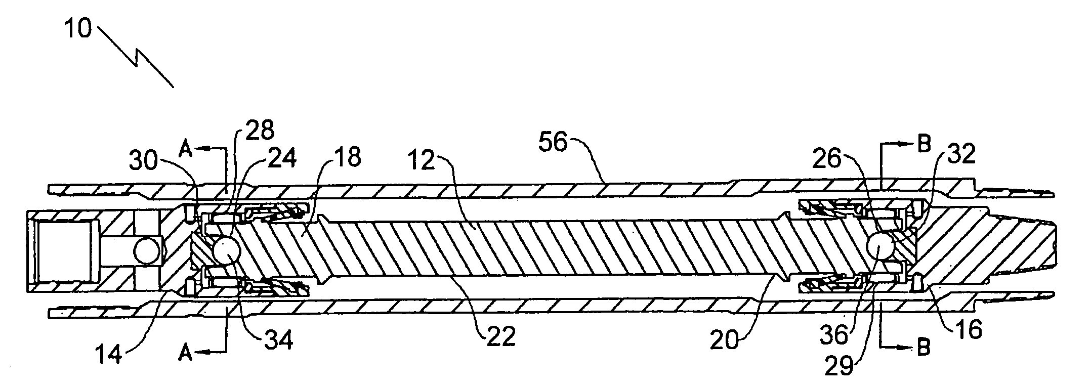
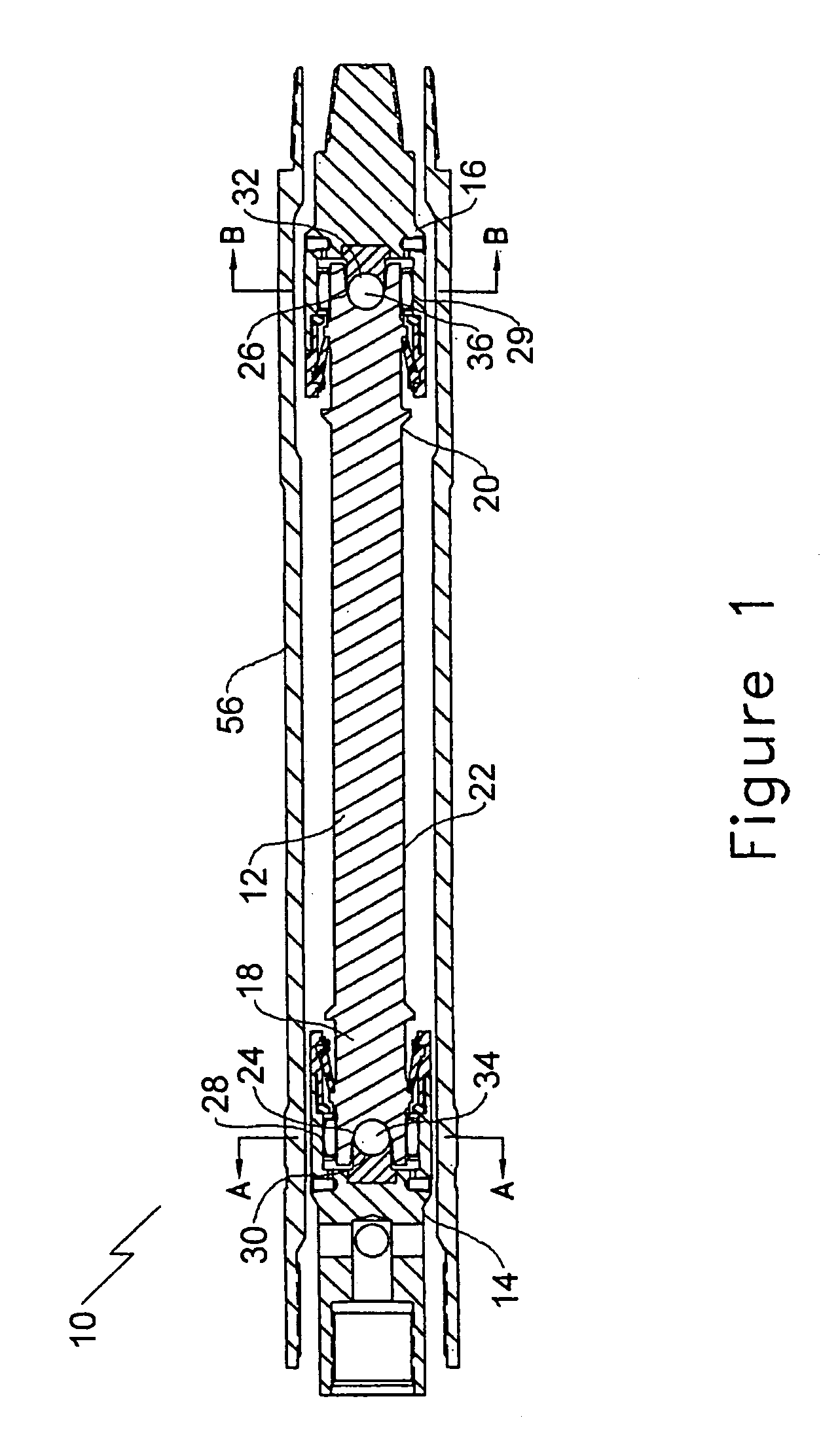
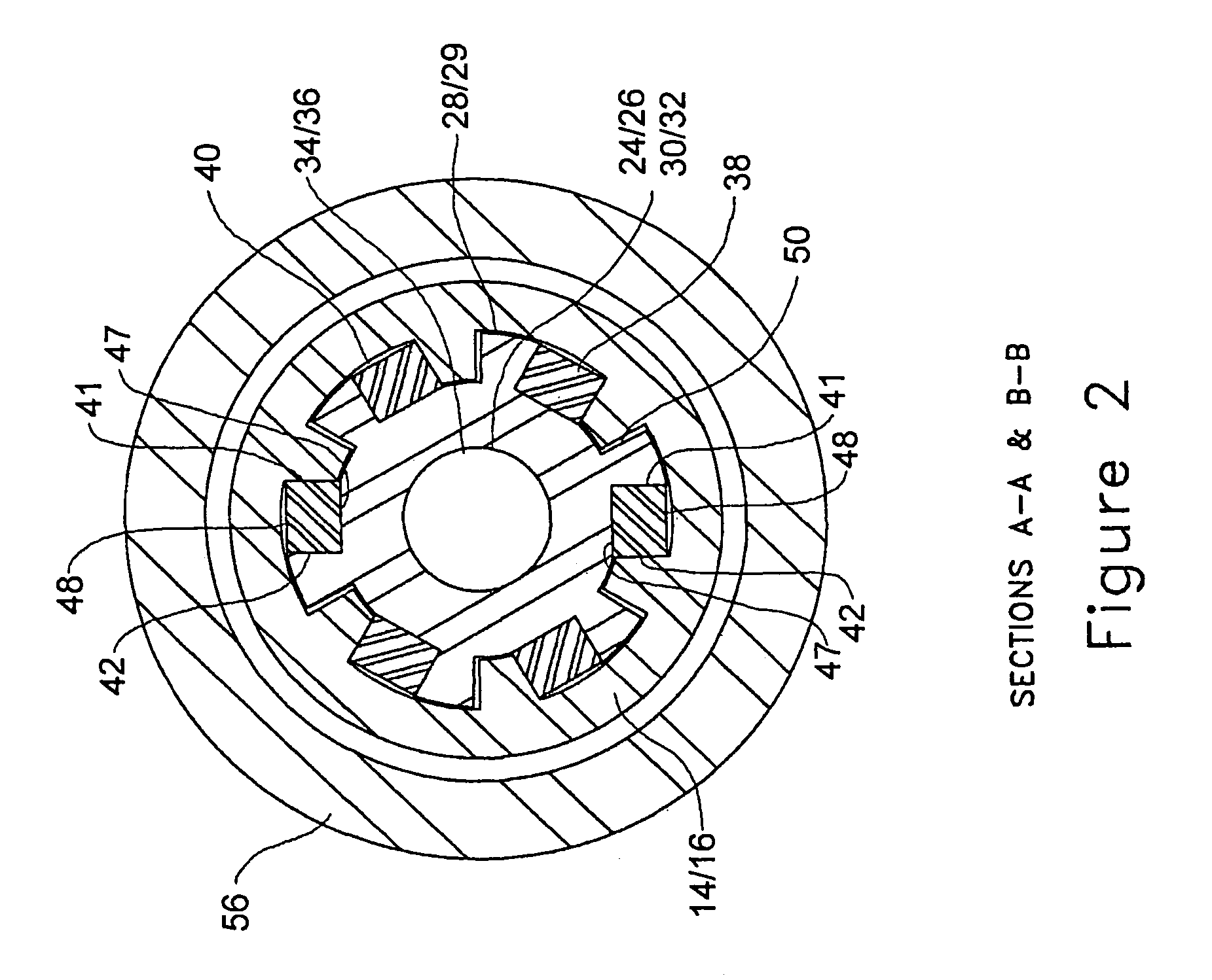
[0015]Referring to FIG. 1, drive line 10 includes a central shaft 12 and two end housings 14 and 16. Central shaft 12 has opposed ends 18 and 20 and an exterior surface 22. A ball seat 24 and 26 is provided at each of opposed ends 18 and 20 of shaft 12. End housings 14 and 16 each have an interior surface 28 and 29 and a centrally disposed ball seat 30 and 32. Balls 34 and 36 are positioned between ball seats 24 and 26 at each of opposed ends 18 and 20, respectively, of shaft 12 and ball seats 30 and 32 in end housings 14 and 16, thereby facilitating omni-directional pivotal movement between shaft 12 and end housings 14 and 16. Referring now to FIGS. 3 and 4, a plurality of elongate keys 38 extend radially from exterior surface 22 of shaft 12 at each of opposed ends 18 ...