
Methods and structures for reducing lateral diffusion through cooperative barrier layers

a barrier layer and cooperative technology, applied in the field of structures, can solve the problems of limiting the lifetime of devices, and the components of various other organic optoelectronic devices are likewise susceptible to attack from exterior environmental species, so as to reduce adverse effects

Inactive Publication Date: 2007-03-06
UNIVERSAL DISPLAY
View PDF44 Cites 56 Cited by
  • Summary
  • Abstract
  • Description
  • Claims
  • Application Information

AI Technical Summary

Benefits of technology

[0012]One advantage of the present invention is that organic optoelectronic structures are produced that provide an effective barrier between the organic optoelectronic device and the ambient atmosphere, reducing adverse effects due to chemical species in the ambient atmosphere, such as moisture and oxygen.
[0013]Another advantage of the present invention is that organic optoelectronic structures are provided that address problems associated with lateral diffusion of moisture and oxygen within their barrier layers.
[0014]These and other embodiments and advantages of the present invention will become readily apparent to those of ordinary skill in the art upon review of the disclosure to follow.

Problems solved by technology

However, metals and their interface with the organic material are susceptible to oxygen and moisture, which can severely limit the lifetime of the devices.
Components of various other organic optoelectronic devices (e.g., organic electrochromic displays, organic photovoltaic devices and organic thin film transistors) are likewise susceptible to attack from exterior environmental species, including water and oxygen.

Method used


Image

  • Methods and structures for reducing lateral diffusion through cooperative barrier layers
  • Methods and structures for reducing lateral diffusion through cooperative barrier layers
  • Methods and structures for reducing lateral diffusion through cooperative barrier layers

Examples


Embodiment Construction

[0027]The present invention now will be described more fully hereinafter with reference to the accompanying drawings in which preferred embodiments of the invention are shown. This invention may, however, be embodied in different forms and should not be construed as limited to the embodiments set forth herein.

[0028]As used herein, a “layer” of a given material includes a region of that material whose thickness is small compared to both its length and width. Examples of layers include sheets, foils, films, laminations, coatings, and so forth. As used herein a layer need not be planar, but can be bent, folded or otherwise contoured, for example, to at least partially envelop another component.

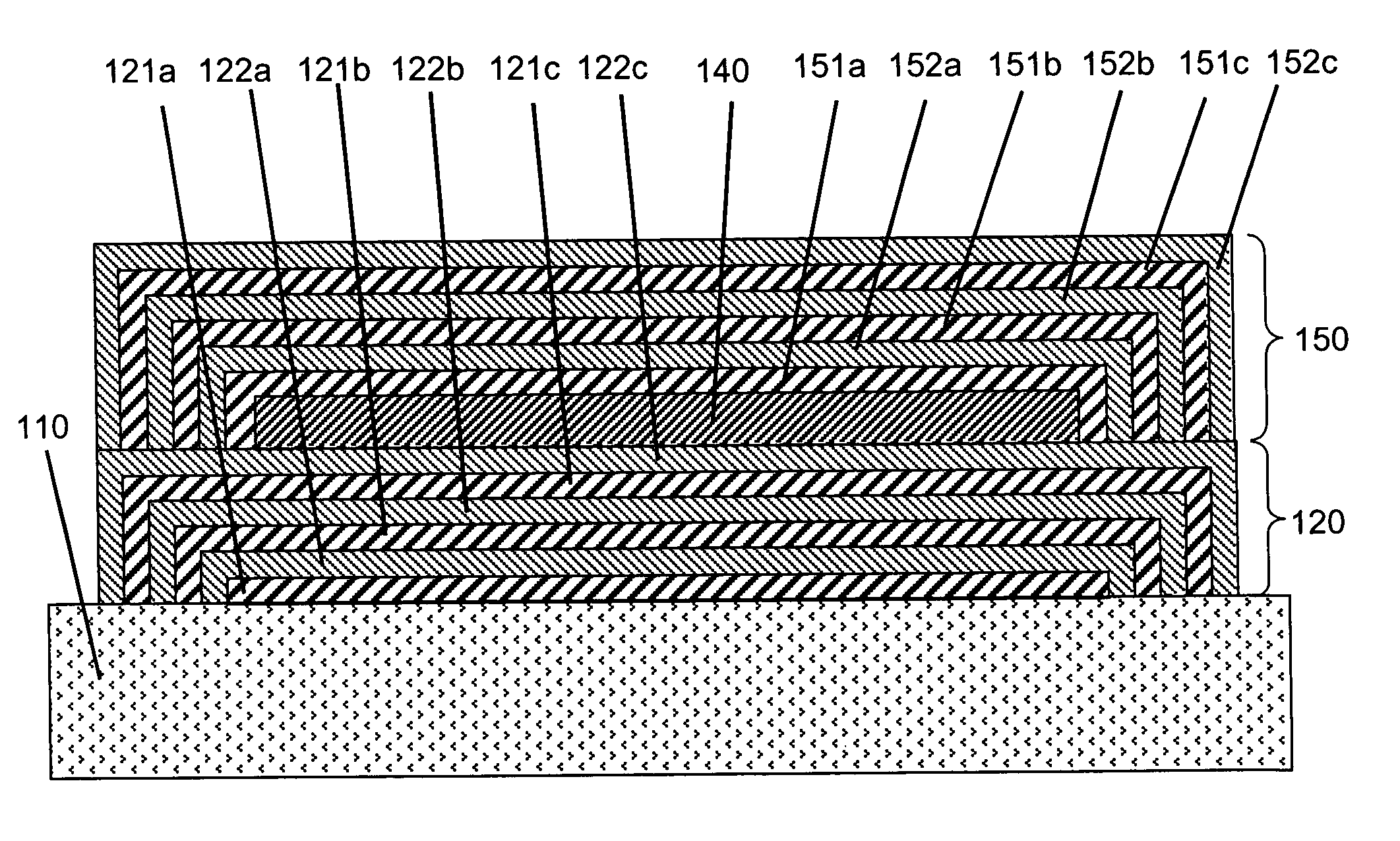
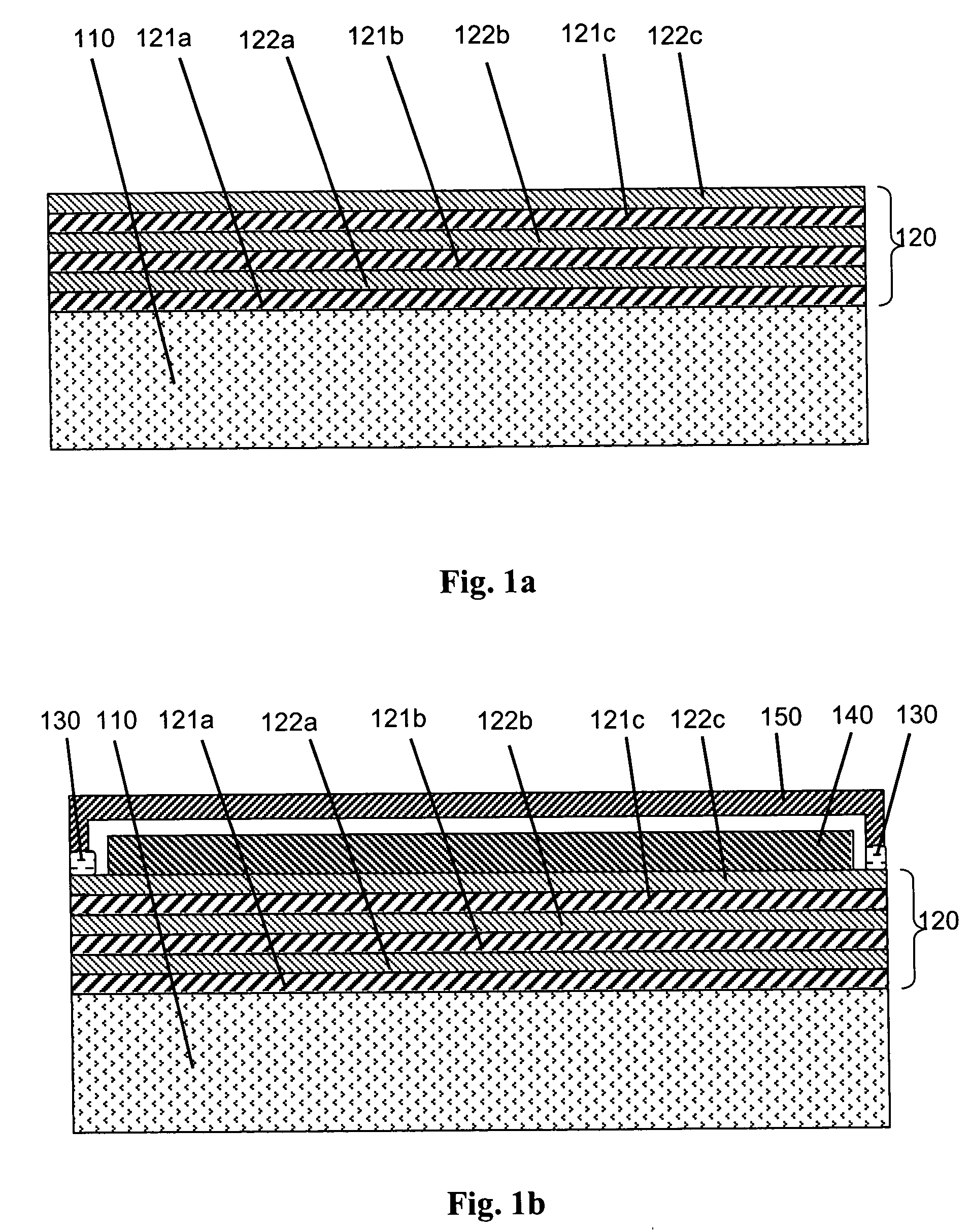
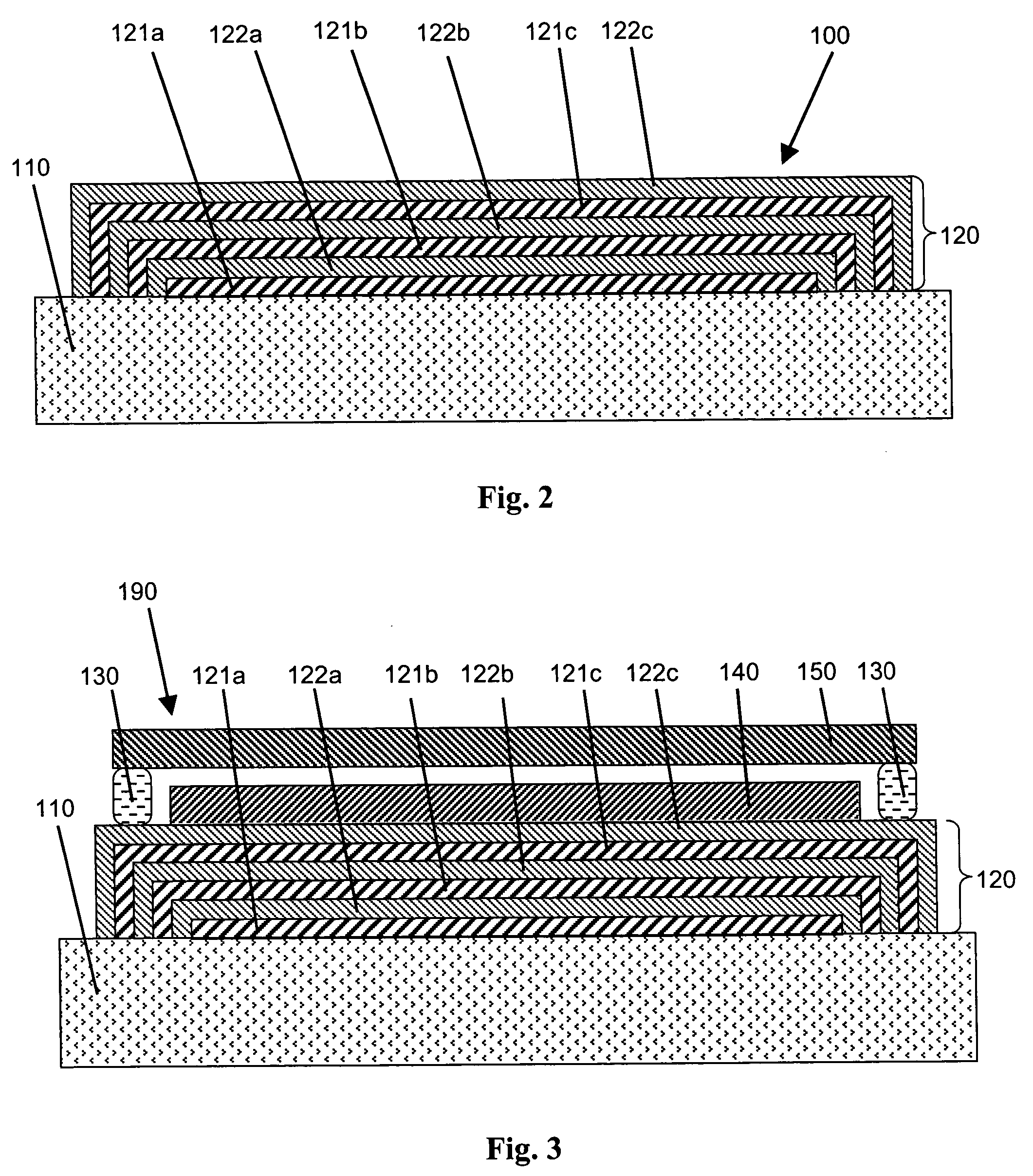
[0029]Referring now to FIG. 2, a covered substrate 100 is shown in accordance with an embodiment of the invention. The covered substrate 100 includes a substrate layer 110 and a barrier region 120 (which is composed of multiple cooperative barrier layers as discussed below) disposed on the substr...


PUM


Abstract

A covered substrate is described, which comprises: (a) a flexible substrate layer; and (b) a plurality of cooperative barrier layers disposed on the substrate layer. The plurality of cooperative barrier layers further comprise one or more planarizing layers and one or more high-density layers. Moreover, at least one high-density layer is disposed over at least one planarizing layer in a manner such that the at least one high-density layer extends to the substrate layer and cooperates with the substrate layer to completely surround the at least one planarizing layer. When combined with an additional barrier region, such covered substrates are effective for enclosing organic optoelectronic devices, such organic light emitting diodes, organic electrochromic displays, organic photovoltaic devices and organic thin film transistors. Preferred organic optoelectronic devices are organic light emitting diodes.

Description

STATEMENT OF RELATED APPLICATION[0001]This is a continuation of U.S. patent application Ser. No. 09 / 820,540, filed Mar. 29, 2001, and entitled “Methods and Structures for Reducing Lateral Diffusion through Cooperative Barrier Layers.” now U.S. Pat. No. 6,664,137.FIELD OF THE INVENTION[0002]The present invention relates to structures that protect organic optoelectronic devices from the surrounding environment.BACKGROUND OF THE INVENTION[0003]Organic optoelectronic devices, including circuits, such as organic light emitting diodes, organic electrochromic displays, organic photovoltaic devices and organic thin film transistors, are known in the art and are becoming increasingly important from an economic standpoint.[0004]As a specific example, organic light emitting devices (“OLEDs”), including both polymer and small-molecule OLEDs, are potential candidates for a great variety of virtual- and direct-view type displays, such as lap-top computers, televisions, digital watches, telephones...

Claims


Application Information

Patent Timeline
Patent Type & Authority Patents(United States)
IPC IPC(8): H05B33/00H10K99/00
CPCH01L25/047H01L51/0097H01L51/448H01L51/5256Y10T428/24628Y02E10/549Y10T428/24669Y10T428/24174H01L2924/0002Y10T428/31931Y10T428/31786Y10T428/3154Y10T428/31938Y10T428/31667Y10T428/31855Y10T428/31721Y10T428/31507H10K77/111H10K30/88H10K50/8445H01L2924/00H10K39/601
Inventor WEAVER, MICHAEL STUART
Owner UNIVERSAL DISPLAY
Learn More