Organic electroluminescent display device and driving method thereof

a display device and electroluminescent technology, applied in static indicating devices, electroluminescent light sources, instruments, etc., can solve the problems of reducing speed, reducing display size of passive matrix organic el display devices, and requiring a relatively high amount of power to operate, so as to reduce power consumption, reduce operation speed, and improve aging efficiency

Active Publication Date: 2007-03-06
LG DISPLAY CO LTD
View PDF7 Cites 6 Cited by
  • Summary
  • Abstract
  • Description
  • Claims
  • Application Information

AI Technical Summary

Benefits of technology

[0020]An object of the present invention is to provide an organic electroluminescent display device where a reverse bias is applied to an organic electroluminescent diode without reduction of operation speed and increase of power consumption, and a driving method thereof.
[0021]Another object of the present invention is to provide an organic electroluminescent display device where an aging efficiency is improved by reducing a load, and a driving method thereof.

Problems solved by technology

While both the passive matrix organic EL display device and the active matrix organic EL display device have simple structures and are formed by a simple fabricating process, the passive matrix organic EL display device requires a relatively high amount of power to operate.
In addition, the display size of a passive matrix organic EL display device is limited by its structure.
Accordingly, an operation speed is reduced and a power consumption increases, thereby reducing an aging efficiency.

Method used


Image

  • Organic electroluminescent display device and driving method thereof
  • Organic electroluminescent display device and driving method thereof
  • Organic electroluminescent display device and driving method thereof

Examples


Embodiment Construction

[0034]Reference will now be made in detail to the preferred embodiments of the present invention, examples of which are illustrated in the accompanying drawings.

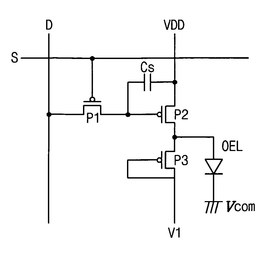
[0035]FIG. 4 is a circuit diagram showing an organic electroluminescent display device according to an embodiment of the present invention. In FIG. 4, an organic EL display device includes a gate line “S” crossing a data line “D,” thereby defining a pixel region. Even though only a single gate line and a single data line are shown, the organic EL display device may include a plurality of gate lines and a plurality of data lines, thereby defining a plurality of pixel regions. Each pixel region includes first, second and third transistors “P1,”“P2” and “P3”, a storage capacitor “CS” and an organic electroluminescent (EL) diode “OEL.” The first, second and third transistors “P1,”“P2” and “P3” may be positive (P) type thin film transistors.

[0036]In particular, the first transistor “P1” connected to the gate line “S” and the data...


PUM


Abstract

An organic electroluminescent display device includes a gate line receiving a gate signal, a data line crossing the gate line, the data line receiving a data signal, a first transistor switching the data signal according to the gate signal, the first transistor being turned on during a single horizontal scan time period having first and second sub-periods, a second transistor switching a source voltage according to the data signal and connected to the first transistor, a storage capacitor connected to a first node between the first and second transistors and connected to the source voltage, a third transistor switching a first voltage signal and connected to the second transistor, the first voltage signal having different voltage levels during the first and second sub-periods of the scan time period, and an organic electroluminescent diode connected to a second node between the second and third transistors and connected to a ground voltage.

Description

BACKGROUND OF THE INVENTION[0001]1. Field of the Invention[0002]The present invention relates to an organic electroluminescent display device, and more particularly, to an organic electroluminescent display device having a lengthened life time and a stability in operation and a driving method thereof.[0003]2. Discussion of the Related Art[0004]Among flat panel displays (FPDs), organic electroluminescent (EL) devices have been of particular interest in research and development because they are self-light-emitting type displays having a wide viewing angle as well as a high contrast ratio in comparison to liquid crystal display (LCD) devices. Organic EL devices are lightweight and small, as compared to other types of display devices, because they do not need a backlight. Organic EL devices have other desirable characteristics, such as low power consumption, superior brightness and fast response time. When driving the organic EL devices, only a low direct current (DC) voltage is require...

Claims


Application Information

Patent Timeline
Patent Type & Authority Patents(United States)
IPC IPC(8): G09G3/10G09G5/10H05B33/00
CPCG09G3/3233G09G3/3291G09G2310/0256G09G2300/0809G09G2300/0842G09G2300/043H05B33/00
Inventor OH, DU-HWAN
Owner LG DISPLAY CO LTD
Why Eureka
Try Eureka