Light-guiding module

a technology of light-guiding modules and light-guiding plates, which is applied in the direction of waveguides, optical waveguide light guides, instruments, etc., can solve the problems of wasting a lot of time, further reducing the lighting uniformity of the light-guiding plate, and complex assembly process, so as to improve the efficiency of the manufacturing process, reduce the cost of the module, and simplify the manufacturing process

Inactive Publication Date: 2007-03-06
KUO HENG SHENG
View PDF4 Cites 4 Cited by
  • Summary
  • Abstract
  • Description
  • Claims
  • Application Information

AI Technical Summary

Benefits of technology

[0010]One aspect of a light-guiding module of the present invention is to achieve the light guiding and reflection function, which can reduces the cost of the module. The present invention simplifies the manufacturing process, improves the efficiency of the manufacturing process and increases lighting uniformity and illumination.

Problems solved by technology

However, this wastes a lot of time, and, furthermore, the adhesive impedes illumination, causing a further decrease in the lighting uniformity of the light-guiding plate 1a.
The third drawback of the conventional method is the complex nature of the assembly process.
In practice, this method is highly complex and inconvenient, requiring an unnecessarily long assembly time and thereby adding to production costs.

Method used


Image

  • Light-guiding module
  • Light-guiding module
  • Light-guiding module

Examples


second embodiment

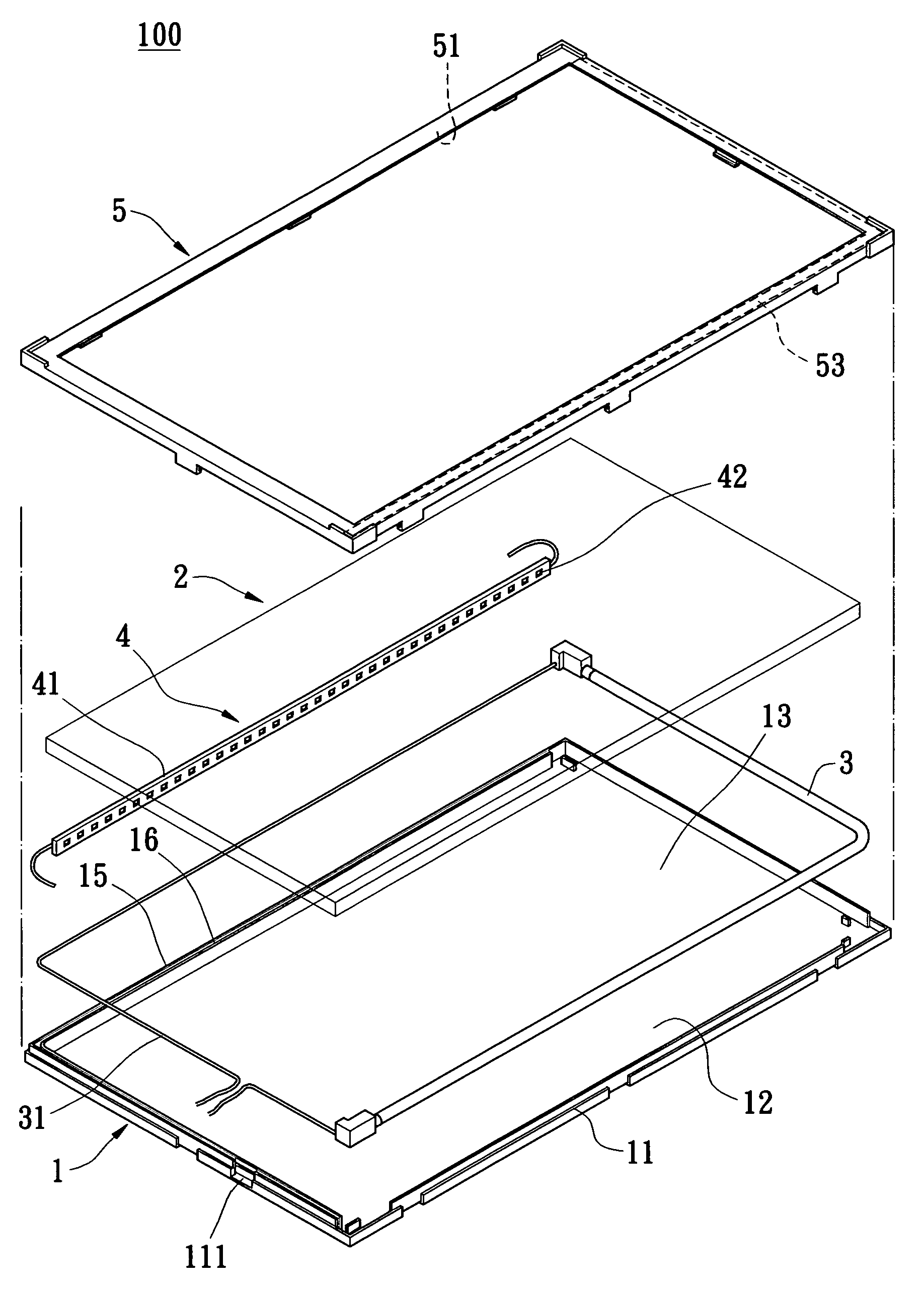
[0036]Referring to FIG. 10A, the light-guiding plate 2 of the first and second embodiment has a recess 21 corresponding to the lamp 3. The lamp 3 is received in the recess 21. The light emanating from lamp 3 can shine from upper and left light of the lamp to the light-guiding plate 2. In addition, because of the design of the recess, additional light from the lamp 3 shines into the light guiding plate thereby increasing the brightness of the display. So, in other words, there is no need for the reflection sheet 52 of the prior art disposed on the bottom surface 51 of the frame 5. As such, this can be removed from the design, reducing production costs.

[0037]Referring to FIG. 6, a third embodiment is disclosed In this embodiment, the structure of the light-guiding module 100 is same as the first embodiment except for a lamp and a partition. The lamp 3 is L-shaped (double-crook formed); the partition 15 of the reflection cover 1 is also L-shaped. This design allows the straight lamp 3 ...

third embodiment

[0038]In the third embodiment the lamp 3 is L-shaped. As such, the L-shaped reflection sheet 53 must correspond to the L-shaped lamp 3. If the bottom surface 51 of the frame 5 further includes a reflection sheet, the upper part the L-shaped lamp 3 can reflect light.

[0039]Referring to FIGS. 7, 7A and 8, a light-guiding module of the fourth embodiment is disclosed. The structure of the light-guiding module 100 is same as the third embodiment and further comprises a LED lighting module 4. The LED lighting module 4 is disposed between another inner side of the receiving part 13 and another side of the light-guiding plate 2. The LED lighting module 4 is disposed on the side of the light-guiding plate 2 corresponding to a double-crooked formed section of the L-shaped lamp 3. This design allows for the lighting mechanism of the light-guiding module 100 to further include both the lamp 3 and LED lighting module 4. The LED lighting module 4 is disposed between the side of the light-guiding p...


PUM


Abstract

A light-guiding module, which, with a diffusion sheet and a prism sheet (or a diffusion sheet and a brightness enhancement film), forms a backlighting module that includes a reflection cover, a light-guiding plate and at least one lighting mechanism. The reflection cover has a receiving part and reflects light. The light-guiding plate is transparent, and the light-guiding plate receives the receiving part of the reflection cover. The lighting mechanism receives the receiving part of the reflection cover, and the lighting mechanism is disposed between the side of the light-guiding plate and the inner-side of the receiving part. The frame is cover by the reflection cover.

Description

BACKGROUND OF THE INVENTION[0001]1. Field of the Invention[0002]The present invention relates to a light-guiding module. In particularly the present invention relates to combine a reflection unit with a light-guiding plate.[0003]2. Description of Related Art[0004]A backlight module uses as a backlight source, and is applied broadly to various information, communication and consumer products, such as LCDs, film scanners, filmstrips or overhead projectors. The LCD field is the main application of the backlight module and has flourished recently, so that the components of the backlight module are becoming more and more important. How to reduce the cost of materials, shorten the time needed for assembly, improve manufacturing efficiency, increase the lighting uniformity, and increase the illumination are the main issues that need to be solved in this field.[0005]The backlight module comprises a light source, a light-guiding plate, a reflection sheet, a diffusion sheet, a prism sheet (or...

Claims


Application Information

Patent Timeline
Patent Type & Authority Patents(United States)
IPC IPC(8): G02B6/10
CPCG02B6/009G02B6/0068G02B6/0071Y10S385/901G02B6/0091
Inventor KUO, HENG-SHENG
Owner KUO HENG SHENG
Why Eureka
Try Eureka