Optical module

a technology of optical modules and optical components, applied in the field of optical modules, can solve the problems of comparatively expensive materials and electrical defects, and achieve the effects of facilitating substrate positioning, enhancing thermal dissipation characteristics, and affecting manufacturing

Active Publication Date: 2006-07-11
SUMITOMO ELECTRIC IND LTD
View PDF14 Cites 5 Cited by
  • Summary
  • Abstract
  • Description
  • Claims
  • Application Information

AI Technical Summary

Benefits of technology

[0007]Since the optical module thus configured provides the base extending along the predetermined axis from the stem and the substrate is mounted on the base, heat generated by the semiconductor optical device is transmitted to the base via the stem and heat generated by electronic components constituting the electronic circuit and mounted on the substrate is directly transmitted to the base, thereby facilitating heat dissipation.
[0008]In the present optical module, the stem may be made of a first material, and the base may be made of a second material. Conventional module has a stem made of CuW, which is comparatively costly material. Since the present invention has the base made of different material to the stem, the base may be made of relatively economical material, such as aluminum, thereby reducing the cost of the module without fang the effective heat dissipation.
[0009]In the optical module, an edge portion of the base may contain the same material as that constituting the stem. When the stem and the base are made of different material, a thermal stress between the lead terminals and the substrate, which originates in different thermal expansion co-efficient of respective materials, may bring an electrical defect therebetween. By containing the same material as the stem in a edge portion of the base, a stress induced between the lead terminals and the substrate may relax, thereby enhancing the reliability of the module.
[0010]The ingredient of the first material to the second material at the edge portion may gradually decrease from the stem to the portion apart therefrom. This configuration further relaxes the discrepant thermal expansion co-efficient.
[0012]The stem and the base are preferably made of the same material and are formed in unity. This enhances the thermal dissipation characteristic without taking the thermal expansion co-efficient into account.
[0013]The lead terminals and the base preferably sandwich the substrate therebetween, which facilitates the positioning of the substrate and effects the manufacturing.

Problems solved by technology

Conventional module has a stem made of CuW, which is comparatively costly material.
When the stem and the base are made of different material, a thermal stress between the lead terminals and the substrate, which originates in different thermal expansion co-efficient of respective materials, may bring an electrical defect therebetween.

Method used


Image

  • Optical module
  • Optical module
  • Optical module

Examples


Embodiment Construction

[0019]Preferred embodiments of the present invention will be described as referring to accompany drawings. In the description of drawings, elements identical to each other will be referred to with numerals identical to each other without overlapping explanations.

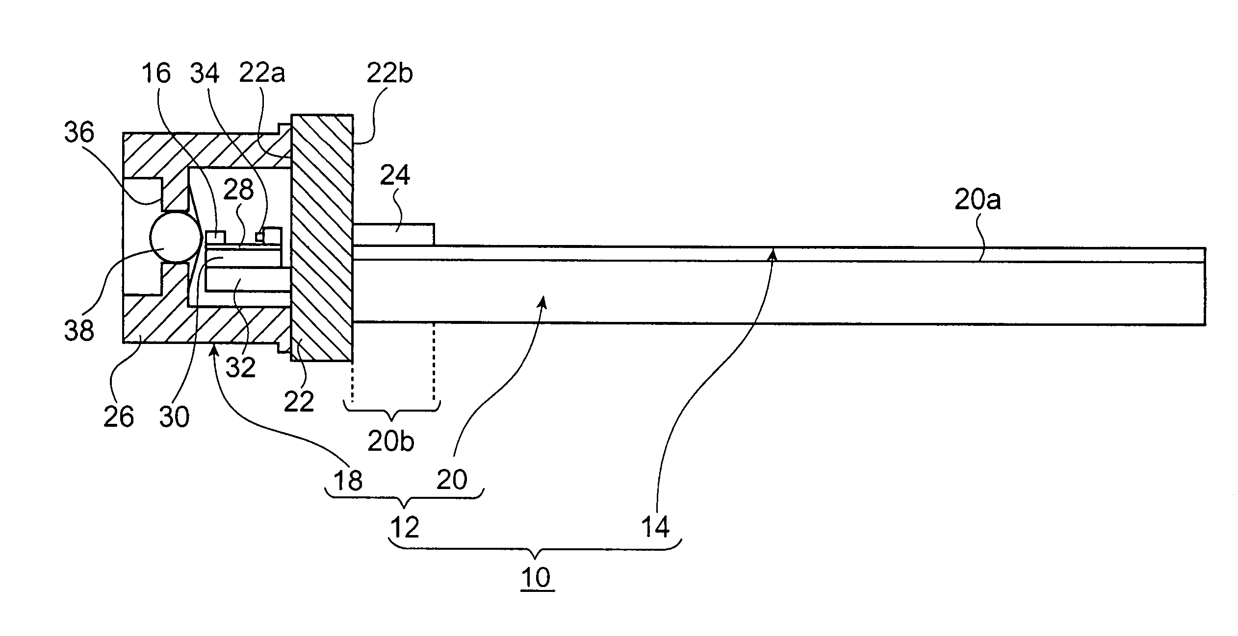
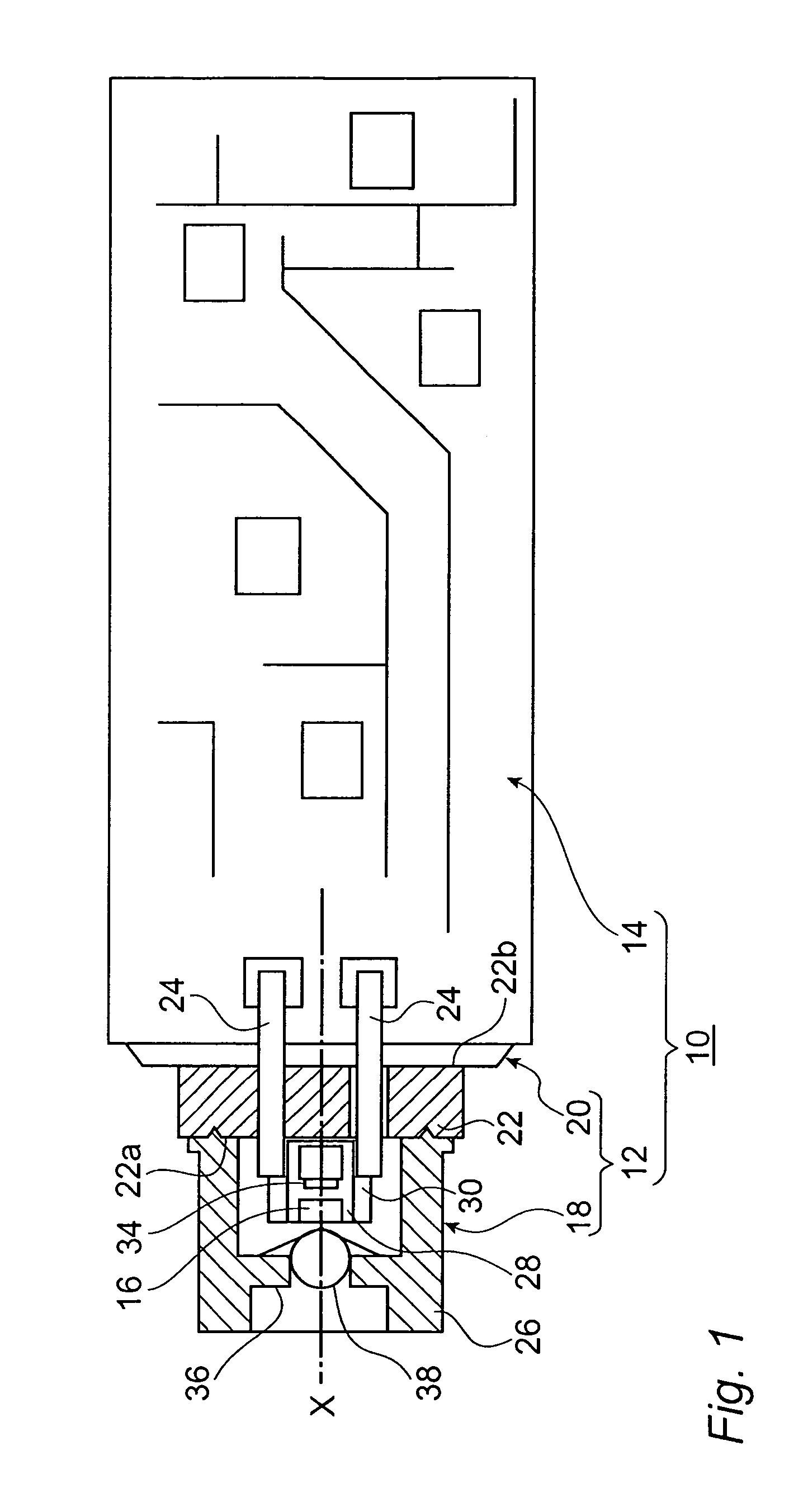
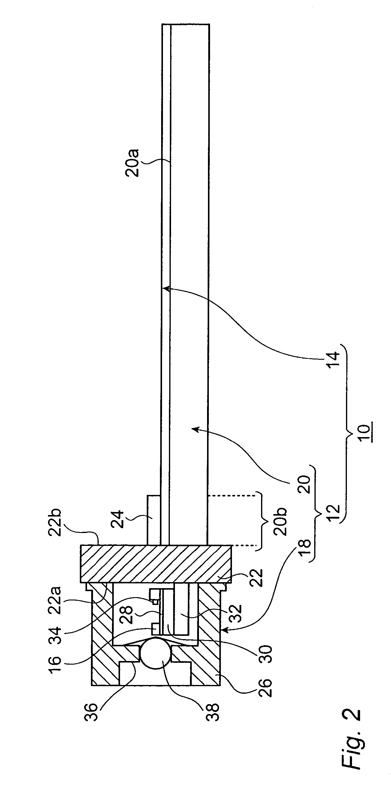
[0020]FIG. 1 is a plan view of a light-emitting module 10 according to the present embodiment and FIG. 2 is a side view of the light-emitting module 10. In FIGS. 1 and 2, a package 12 of the light-emitting module is partially cross-sectional view to show the inside configuration.

[0021]As shown in FIG. 1 and FIG. 2, the light-emitting module 10 comprises a package 12 and a substrate 14. The package 12 has a primary portion 18 for enclosing a semiconductor laser 16 and a base 20 for mounting the substrate 14.

[0022]The primary 18 includes a stem 22, the semiconductor laser 16, a plurality of lead terminals 24 and a casing 26 of a can type. The stem 22 is made of a metal such as CuW, Kovar and iron, and has a shape of a disk. Th...


PUM


Abstract

The present invention provides an optical module with effective thermal dissipation characteristic. The present optical module comprises a semiconductor optical device, a stem, plural lead terminals, a substrate and a base. The stem mounts the semiconductor optical device. The lead terminals extend along a predetermined axis from the stem. The base mounts the substrate on which an electronic circuit is provided. The edge portion of the base adjacent to the stem is made of a material containing the same ingredient as that contained in the stem, or the stem and the base are formed in unity.

Description

BACKGROUND OF THE INVENTION[0001]1. Field of Invention[0002]This invention relates to an optical module and an optical network using the same.[0003]2. Related Prior Art[0004]A semiconductor laser with a can-type package is widely applied in an optical communication system. Such can-type package 82, as shown in FIG. 5, is connected to a substrate 86 via lead terminals 84 and constitutes a light-emitting module 80. The light-emitting module thus formed is installed into a chassis and forms an optical transmitting module disclosed in the Japanese patent laid open 2001-296458. In this patent, an optical transceiver is also disclosed, in which not only the optical-transmitting module but also an optical-receiving module are provided in the chassis.[0005]In the present and future optical communication system, further speed and capacity must be requested and accordingly thermally stable operation will be required to the optical-module used in such high-speed and high-capacity optical syste...

Claims


Application Information

Patent Timeline
Patent Type & Authority Patents(United States)
IPC IPC(8): G02B6/42H01S5/022
CPCG02B6/4201
Inventor OOMORI, HIROTAKA
Owner SUMITOMO ELECTRIC IND LTD
Why Eureka
Try Eureka