Method of making a straddle mount connector

Inactive Publication Date: 2007-03-13
HON HAI PRECISION IND CO LTD
View PDF6 Cites 22 Cited by
  • Summary
  • Abstract
  • Description
  • Claims
  • Application Information

AI Technical Summary

Benefits of technology

[0015]Accordingly, it is an object of the present invention to provide a method of making a straddle mount connector which can be easier applica

Problems solved by technology

Consequently, a printed circuit board mounted within the device becomes small as well.
However, since the diameter of the through holes is relatively large, only a limited number of through holes could be provided in a given area.
Therefore, through-hole technology could not meet the requirement for high density applications.
It is quite difficult to form the opening in the edge surface of the printed circuit board, thereby complicating the manufacturing process.
This leads to a potential stubbing condition upon placement, particularly because the leads are proportioned to be flexible.
This flexibility also results in less accurate side-to-side placement of the leads on pre-soldered pads of the printed circuit board.
In addition, the ground bus does not provide a robust lead-in for receiving the inserted printed circuit board.
This will create great difficulty during the assembly because a front edge of th

Method used


Image

  • Method of making a straddle mount connector
  • Method of making a straddle mount connector
  • Method of making a straddle mount connector

Examples


Embodiment Construction

[0031]Reference will now be made in detail to the preferred embodiment of the present invention.

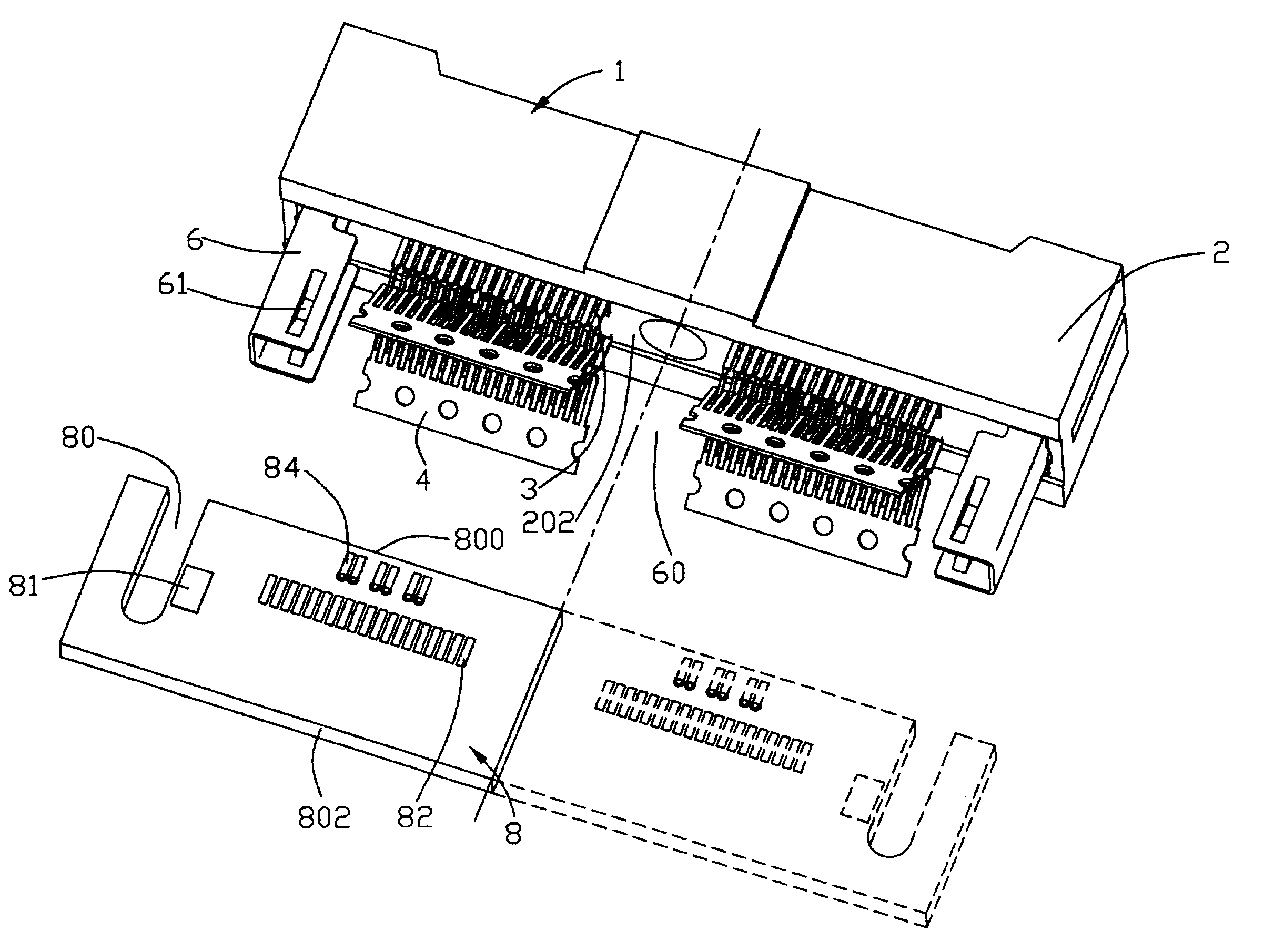
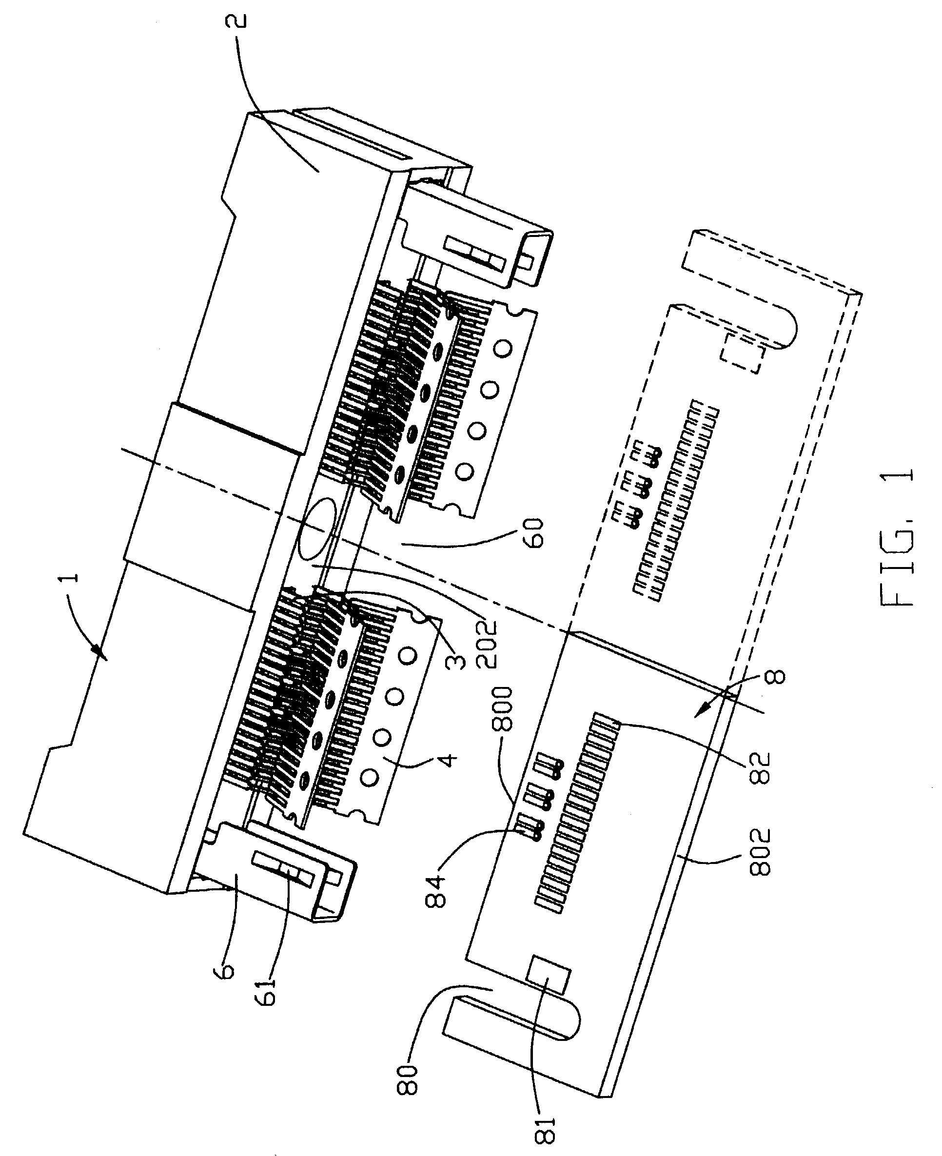
[0032]FIG. 1 shows a straddle mount connector 1 in accordance with the present invention and a printed circuit board 8 on which the connector 1 is to be straddle mounted. For simplicity, only a half of the printed circuit board 8 is shown. It should be noted that this is not a limitation for the embodiment. The printed circuit board 8 defines a pair of channels 80 extending from a mounting edge 800 toward the opposite edge 802 and a plurality of signal pads 82 and ground pads 84 arranged in a staggered manner on opposite sides thereof. The ground pads 84 are closer to the mounting edge 800 of the printed circuit board 8 than the signal pads 82.

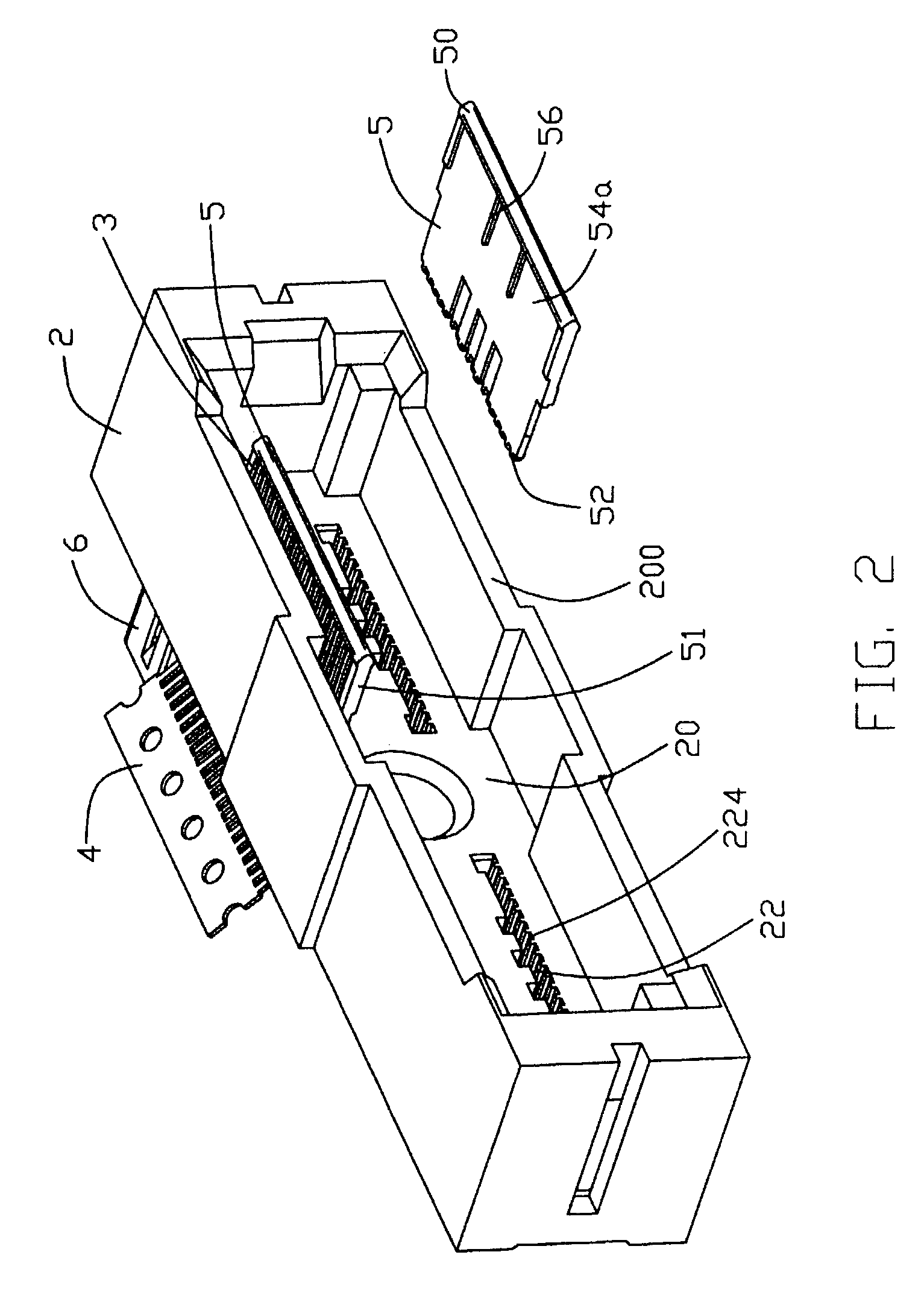
[0033]Further referring to FIGS. 2 and 3, the connector 1 comprises an elongated dielectric housing 2 with two rows of signal contacts 3 and a pair of ground buses 4 provided therein for electrical connection with the printed circuit board 8. The ho...


PUM


Abstract

A method of making an electrical connector includes the steps of: providing a connector body (2) having an insert (5) defining a recessed area (54a) at one side and a number of channels (54b) at an opposite side; assembling a ground bus (4) to the recessed area of the insert, the ground bus including a carrier strip (46) with a number of fingers (460) extending therefrom; assembling a number of signal contacts (3) to the channels of the insert, each signal contact including a board mounting portion (32); and displacing the carrier strip such that each finger extends into space (320) between the mounting portions of two adjacent signal contacts.

Description

CROSS-REFERENCE TO RELATED APPLICATIONS[0001]This patent application is related to two other contemporaneously filed U.S. patent applications entitled “STRADDLE MOUNT CONNECTOR” and entitled “GROUND BUS FOR AN ELECTRICAL CONNECTOR”, invented by the same inventors as this patent application, and all assigned to the same assignee with this application.BACKGROUND OF THE INVENTION[0002]1. Field of the Invention[0003]The present invention relates to a method, and more particularly to a method of making a straddle mount connector in which a lead-in is formed by displacing a carrier strip of a ground bus inserted into the connector.[0004]2. Description of Related Art[0005]There are commonly numerous electrical connectors available from the market and which are mounted to a printed circuit board (PCB) of an electronic device for implementing different functions. In order to meet the needs of the trend toward miniaturizaiton, the overall size of the electronic device becomes smaller and smal...

Claims


Application Information

Patent Timeline
IPC IPC(8): H05K3/20H01R12/16H05K1/11
CPCH01R23/688H05K1/117H05K2201/09409Y10T29/49222Y10T29/49211Y10T29/49208Y10T29/49204Y10T29/49128Y10T29/49169Y10T29/49149H01R13/6585
Inventor KORSUNSKY, IOSIF R.SHIPE, JOANNE E.BROWN, ROBERT W.
Owner HON HAI PRECISION IND CO LTD
Why Eureka
Try Eureka