
Piston arrangement of a hydraulic actuating device on motor vehicles

a technology of hydraulic actuation device and piston, which is applied in the direction of brake action initiation, coupling, braking system, etc., can solve the problems of complicated assembly in two steps, high manufacturing cost of known piston arrangement, and difficult handling of preassembled units consisting of rams and inserts, etc., to simplify manufacturing and assembly.

Inactive Publication Date: 2007-03-13
FTE AUTOMOTIVE GMBH & CO KG
View PDF11 Cites 16 Cited by
  • Summary
  • Abstract
  • Description
  • Claims
  • Application Information

AI Technical Summary

Benefits of technology

This design simplifies assembly, reduces manufacturing costs, and ensures secure attachment of the insert to the piston, preventing pull-out even under high forces without deforming the ball-and-socket joint, allowing for a play-free fit and efficient transmission of forces.

Problems solved by technology

On account of the threaded engagement, this known piston arrangement is expensive to manufacture, and special measures moreover have to be taken in order to prevent loosening of the screw connection.
In terms of the requirements in mass production, assembly in two steps is complicated, wherein the handling of the preassembled unit consisting of the ram and the insert is made more difficult on account of the ball-and-socket connection of these parts.

Method used


Image

  • Piston arrangement of a hydraulic actuating device on motor vehicles
  • Piston arrangement of a hydraulic actuating device on motor vehicles
  • Piston arrangement of a hydraulic actuating device on motor vehicles

Examples


Embodiment Construction

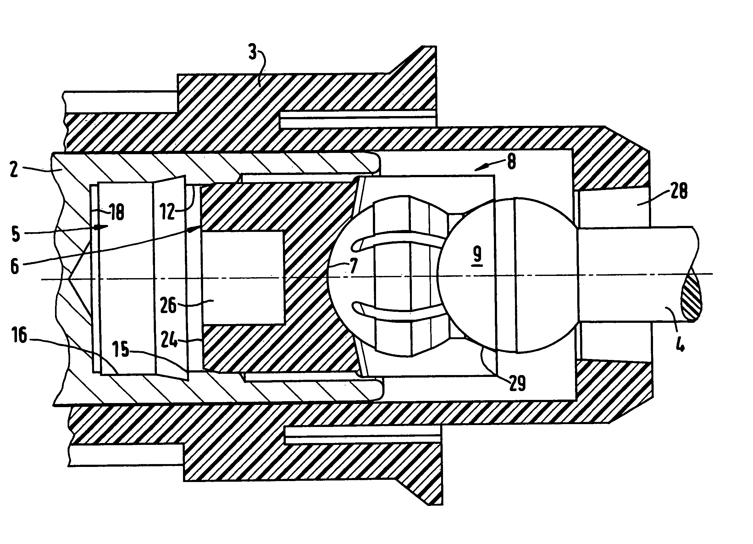
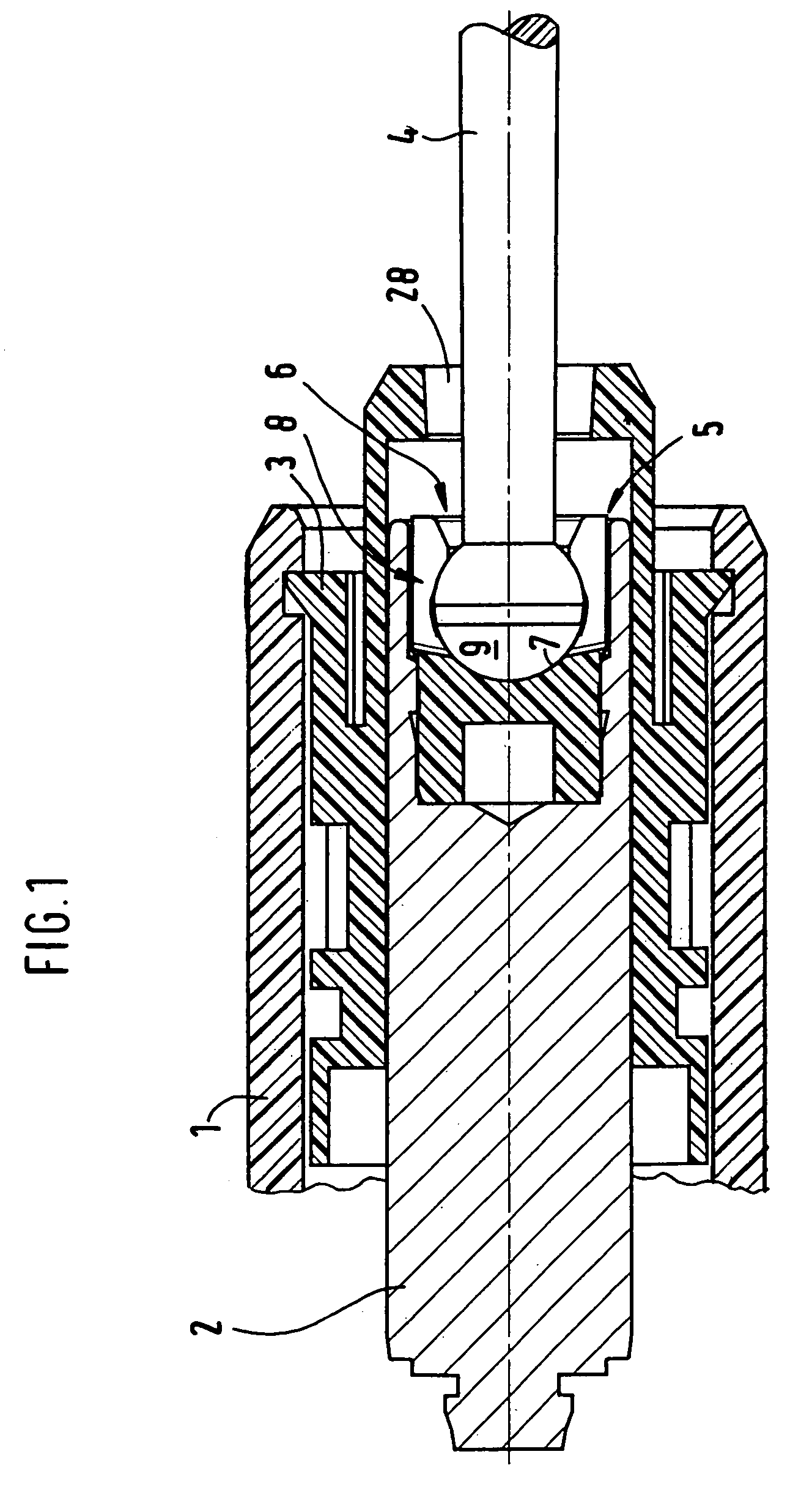
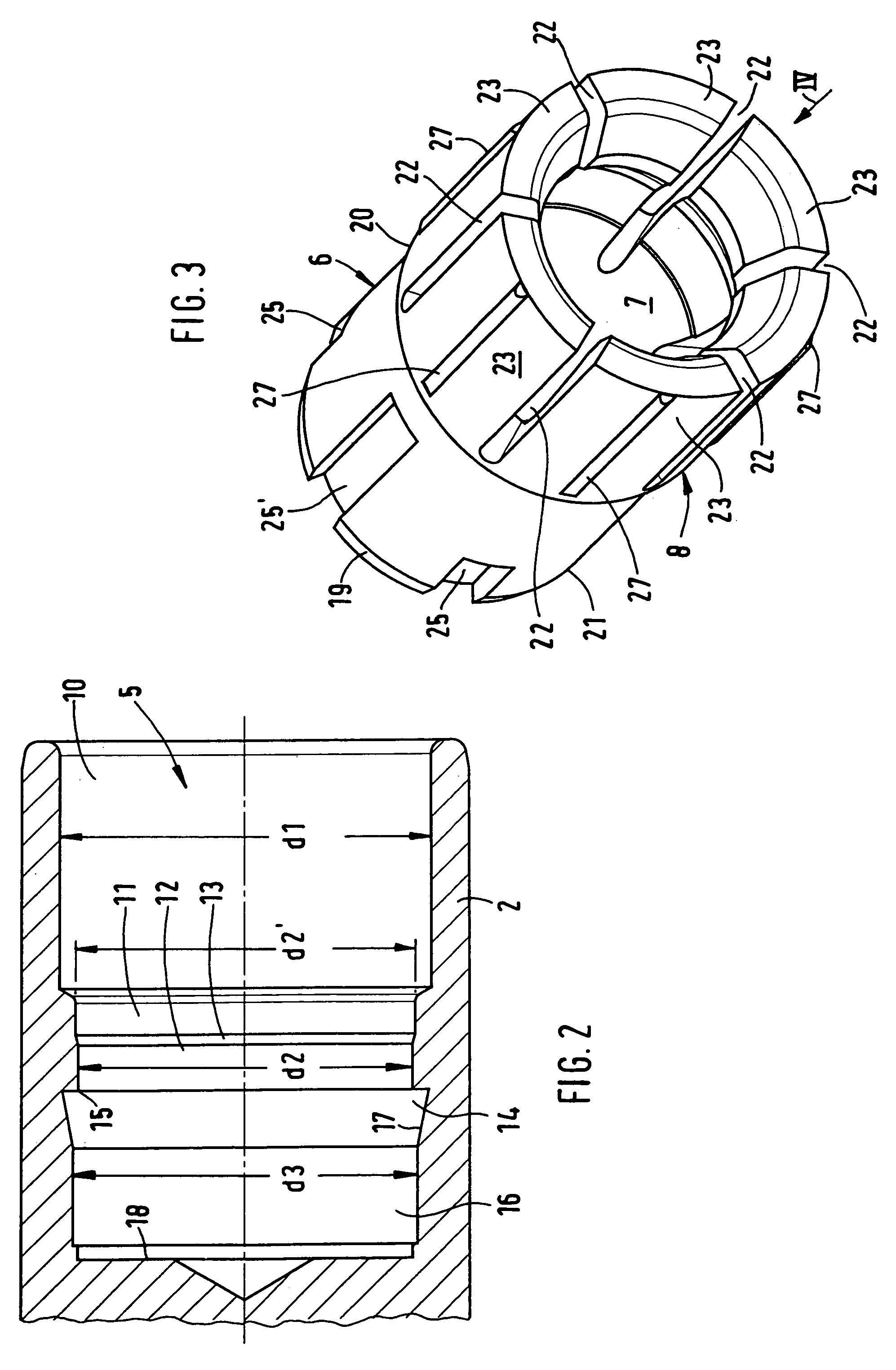
[0030]The piston arrangement, the parts of the master or slave cylinder connected thereto and its individual parts are shown in the drawings on an enlarged scale compared to the actual dimensions for illustrative purposes, wherein FIGS. 2 to 9 are in turn shown on an enlarged scale compared to FIG. 1.

[0031]Of the master or slave cylinder, only the part of the housing 1 which accommodates the piston arrangement is shown broken open in FIG. 1, since the invention does not extend to the design of the master or slave cylinder. The same applies in respect of the arrangement of seals between the housing 1 and the guide sleeve 3 which encloses the piston 2 and the seal arrangements to be fitted at the inner end of the piston 2, none of said seals or seal arrangements being shown in FIG. 1. The piston 2 is a so-called plunger piston which has a cylindrical outer circumferential surface which is guided displaceably in a sealed manner in the guide sleeve 3 and can be moved in the pushing and ...


PUM


Abstract

A piston arrangement for master and / or slave cylinders of a hydraulic actuating device for clutch and / or brake systems on motor vehicles is disclosed. An insert is inserted into a recess of the piston up to a first stop, the insert having a ball seat and an expandable insertion sleeve which is undercut with respect to the ball seat and protrudes with its expandable region. A ram is pushed into the sleeve with its ball end until it snaps into the ball seat. As the ram is further pressed axially, the insert slides over the first stop, is firmly pressed into a narrow hole section of the recess and strikes a second stop at the inner end of the recess. The insertion sleeve is then tightly enclosed by the piston wall and can no longer expand even in the event of very high pull-out forces, i.e. cannot release the ball end of the ram.

Description

BACKGROUND OF THE INVENTION[0001]The invention relates to a piston arrangement for master and / or slave cylinders of a hydraulic actuating device for clutch and / or brake systems on motor vehicles.[0002]In a known piston arrangement of this type (DE 100 62 988 A1), assembly is carried out in two separate steps. Firstly, the snap connection is brought about between the ram and the insert, referred to in said document as the piston link head. The unit preassembled in this way is then inserted into the recess and screwed into the latter by means of a threaded engagement. For this purpose, the recess is provided with an internal thread and the insert is provided with a corresponding external thread. On account of the threaded engagement, this known piston arrangement is expensive to manufacture, and special measures moreover have to be taken in order to prevent loosening of the screw connection. In terms of the requirements in mass production, assembly in two steps is complicated, wherein...

Claims


Application Information

Patent Timeline
Patent Type & Authority Patents(United States)
IPC IPC(8): F16J1/14B60K23/00B60T7/00
CPCF16C11/0623F16C11/069F16J1/22F16D25/088Y10T403/32786F16D2048/0212B60T11/18F16D25/08F16D2025/081
Inventor LIEBIG, DIRKGEBERT, STEFANSPERBER, CHRISTIANSTEINMETZ, HARRY
Owner FTE AUTOMOTIVE GMBH & CO KG
Learn More