Gas generation system

Inactive Publication Date: 2007-03-13
ZODIAC AUTOMOTIVE US
View PDF140 Cites 13 Cited by
  • Summary
  • Abstract
  • Description
  • Claims
  • Application Information

AI Technical Summary

Benefits of technology

[0009]We have identified a need for an gas generation system (e.g., one useful for inflation) wherein an initial gas generation is followed by a sustaining gas generation. In an inflatable member system such as an automotive airbag syst

Problems solved by technology

The output of such an initiator is not rel

Method used


Image

  • Gas generation system
  • Gas generation system
  • Gas generation system

Examples


Embodiment Construction

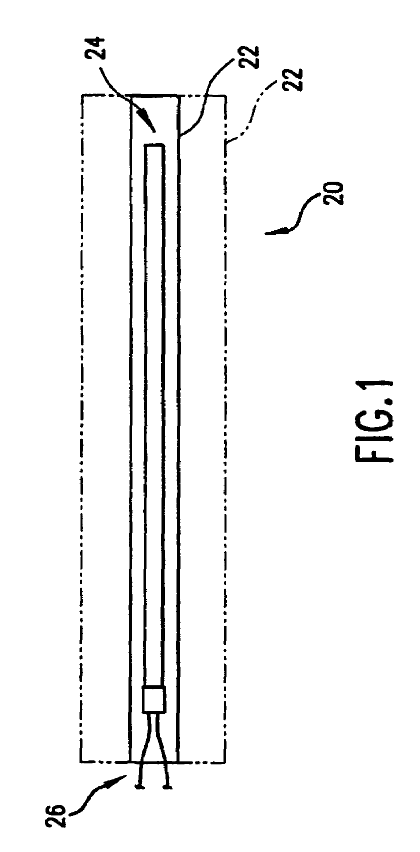
[0025]FIG. 1 shows a system 20 including an inflatable member 22 and a gas generator 24 for generating the gas necessary to inflate the inflatable member. The inflatable member is inflatable from a relatively compact, low internal volume, stowed condition shown in solid lines to a relatively high internal volume deployed condition shown in broken lines. The inflatable member may take any appropriate form such as an expandable metal bladder, an elastic bladder, or a flexible member such as a fabric bag, which, in its stowed condition, may be folded. In the exemplary embodiment, the gas generator is located internal to the inflatable member and is controlled by a pair of leads 26 extending from without to within the inflatable member and connected to an appropriate control system.

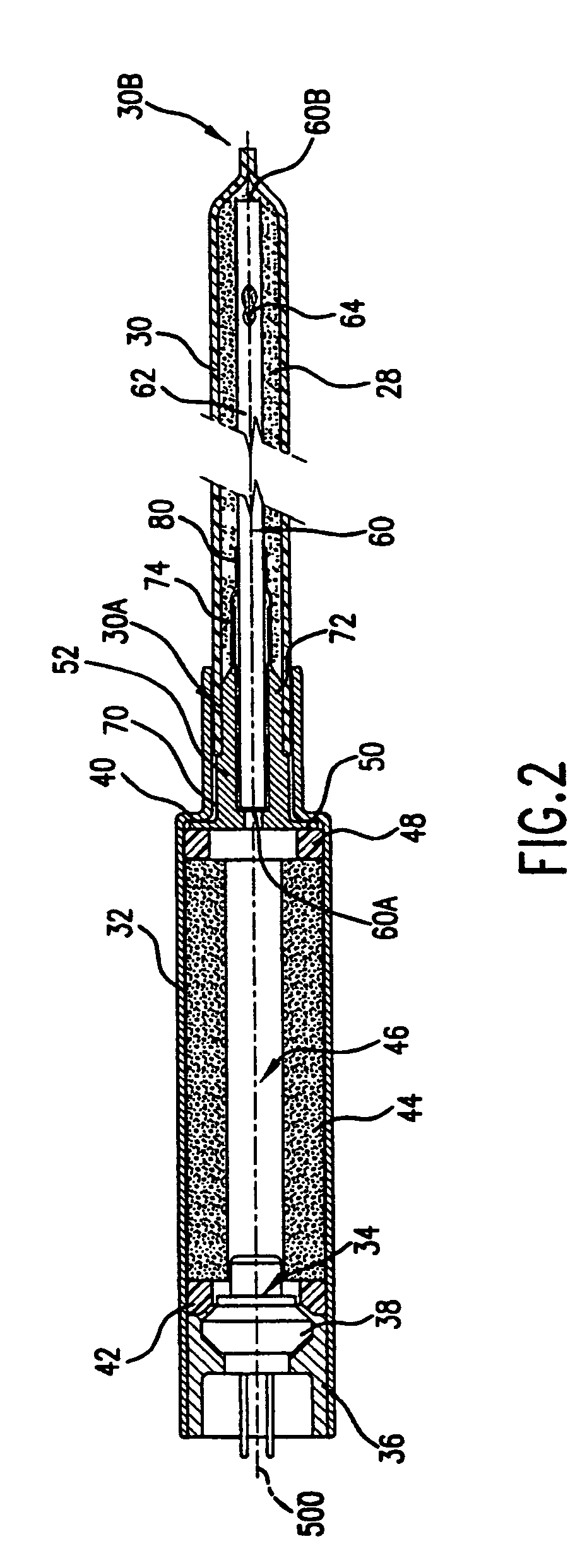
[0026]In the exemplary embodiment of FIG. 2, the generator includes a primary gas generating propellant 28 contained within an elongate flexible member 30 such as a polymeric or metallic tube. The tube 30 has...


PUM


Abstract

A gas generator (24; 140) may be used in an inflatable member system (20) which includes an inflatable member (22) expandable from a stowed condition to a deployed condition. The generator may include a flexible container (30; 150) within the inflatable member, a gas generant (28; 148), initially located within the flexible container, and an initiator (34). A propagating member (60; 142) may be located within the container to permit the initiator to initiate the generant upon triggering of the initiator to inflate the inflatable member from stowed to deployed conditions. A sustainer (44; 152; 156) may be provided to sustain the gas generation and may be positioned within a generator housing upstream of the propagating member or at or adjacent the downstream end of the propagating member.

Description

CROSS-REFERENCE TO RELATED APPLICATION[0001]This patent application is the U.S. national phase of PCT / US00 / 30726 entitled “Gas Generation System” that was filed on Nov. 10, 2000 and published in English on May 17, 2001 and claims priority of U.S. Provisional Patent Application Ser. No. 60 / 165,269 entitled “Gas Generation System” filed on Nov. 12, 1999, the disclosure of which is incorporated by reference herein as if set forth at length.BACKGROUND OF THE INVENTION[0002](1) Field of the Invention[0003]This invention relates to gas generation, and more particularly to gas generation systems useful for inflation purposes.[0004](2) Description of the Related Art[0005]Rapid deflagrating cord (RDC), sometimes erroneously identified as rapid detonating cord has been in common use in the explosives industry as a transfer line for igniting explosives. Detonating cord (detcord) has been used extensively as a transfer line and as an explosive (e.g., for cutting structural elements). Both RDC a...

Claims


Application Information

Patent Timeline
IPC IPC(8): C06D5/00
CPCB60R21/264C06D5/06B60R2021/2633
Inventor ITALIANE, JOHN R.STYNER, JAMES M.NGUYEN, ANDREW C.GREGG, GARY S.HOLLAND, GARY F.WILSON, MICHAEL A.
Owner ZODIAC AUTOMOTIVE US
Why Eureka
Try Eureka