Low-friction pull tape

a pull tape and low friction technology, applied in the field of pull tapes, can solve the problems of difficult positioning of cables within, woven or braided pull tapes encountering significant friction, and the drawing of items through the conduit requires considerable tensile force, so as to reduce friction between the pull tape and the sleev

Active Publication Date: 2007-03-13
FEDERAL MOGUL WORLD WIDE LLC
View PDF13 Cites 36 Cited by
  • Summary
  • Abstract
  • Description
  • Claims
  • Application Information

AI Technical Summary

Benefits of technology

[0007]The invention concerns an elongated pull tape for use within a protective sleeve. The pull tape has a lengthwise direction and comprises a plurality of multifilament first yarns extending in the lengthwise direction. A plurality of multifilament second yarns are interwoven with the first yarns. The second yarns are arranged substantially perpendicularly to the first yarns. A plurality of monofilaments are interwoven with the first and second yarns in the lengthwise direction such that portions of the monofilaments extend over two or more adjacent ones of the second yarns thereby defining a plurality of floats positioned in spaced relation in the lengthwise direction. The floats engage the protective sleeve when the pull tape is pulled therethrough and reduce friction between the pull tape and the sleeve.
[0008]In an alternate embodiment, the pull tape comprises a plurality of monofilaments extending in the lengthwise direction. A plurality of multifilament yarns are interwoven with the monofilaments. The multifilament yarns are arranged substantially perpendicularly to the monofilaments. A portion of the monofilaments extend over two or more adjacent ones of the multifilament yarns, thereby defining a plurality of floats positioned in spaced relation in the lengthwise direction. The floats are engageable with the protective sleeve when the pull tape is pulled therethrough and reduce friction between the pull tape and the sleeve.
[0009]In another embodiment, the pull tape comprises a plurality of first monofilaments extending in the lengthwise direction. A plurality of second monofilaments are interwoven with the first monofilaments, the second monofilaments being arranged substantially perpendicularly to the first monofilaments. Preferably, a portion of the first monofilaments extend over two or more adjacent ones of the second monofilaments, thereby defining a plurality of floats positioned in spaced relation in the lengthwise direction. The floats engage the protective sleeve when the pull tape is pulled therethrough and reduce friction between the pull tape and the sleeve.
[0010]The invention also includes, in combination, an elongated protective sleeve defining an interior space for receiving elongated items and a pull tape located within the interior space. The tape has a lengthwise direction and is slidable within the space for facilitating drawing of elongated items therethrough. The pull tape comprises a plurality of first filamentary members extending in the lengthwise direction and a plurality of second filamentary members interwoven with said first filamentary members. The second filamentary members are arranged substantially perpendicularly to said first filamentary members. A plurality of third filamentary members are interwoven with the first and second filamentary members in the lengthwise direction such that portions of the third filamentary members extend over two or more adjacent ones of the second yarns, thereby defining a plurality of floats positioned in spaced relation in the lengthwise direction. The floats engage the protective sleeve when the pull tape is pulled therethrough and reduce friction between the pull tape and the sleeve.

Problems solved by technology

Once the conduit is in place, for example, underground or throughout a building structure, it is difficult to position cables within it because the interior of the conduit is accessible only at isolated node points where the elongated items are connected to components or where splices are effected.
The conduit may be long and typically does not follow a straight path, and due to the weight of the elongated items and the tortuous path they must follow, drawing of the items through the conduit requires considerable tensile force.
However, it is found that woven or braided pull tapes encounter significant friction as they are drawn through the protective sleeve within the conduit.
The friction between the pull tape and the sleeve increases the force needed for the pull, thus, increasing the chances of a pull tape parting and decreasing the maximum length over which a pull can be effected.
Thus, if a conduit run has too many bends, it may not be feasible to draw a pull tape through it because the pull force required for the draw may exceed the tensile limit of the tape.

Method used


Image

  • Low-friction pull tape
  • Low-friction pull tape
  • Low-friction pull tape

Examples


Embodiment Construction

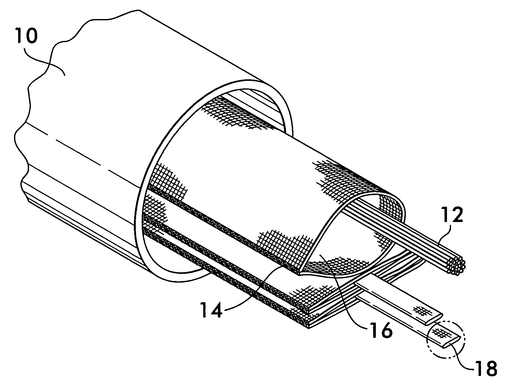
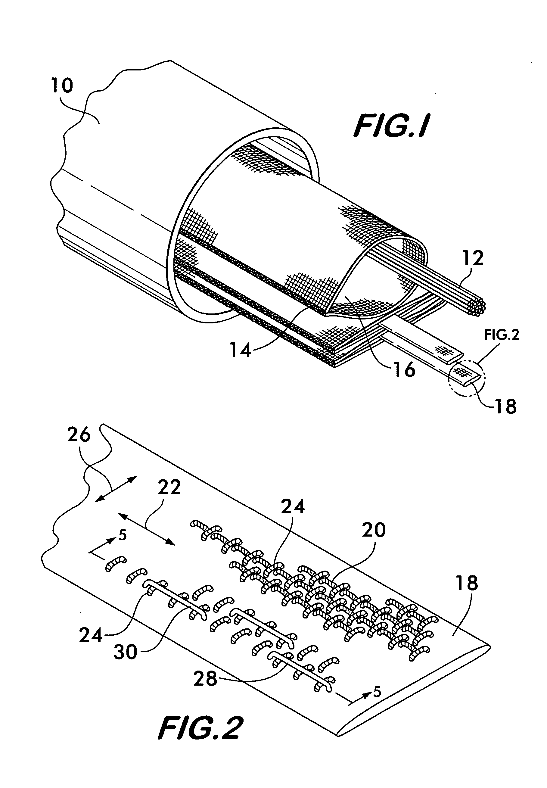
[0016]FIG. 1 shows a conduit 10 for protecting elongated items 12, the elongated items shown schematically representing a wiring harness, a power cable, optical fiber cables or other similar items. A plurality of protective sleeves 14 are positioned within the conduit 10. Sleeves 14 extend over the entire length of the conduit and receive the elongated items 12 within an interior space 16. The sleeves protect the elongated items from abrasion when they are drawn through the sleeve during installation within the conduit 10 and also help organize the space within the conduit, allowing for its efficient use. A pull tape 18 is positioned within each sleeve 14. The pull tape facilitates installation of elongated items 12 within the sleeve. To effect installation, one end of the pull tape is attached to the elongated item and the opposite end is manually pulled or attached to a power winch which draws the pull tape, and consequently, the elongated item through the sleeve, the elongated it...


PUM

PropertyMeasurementUnit
diameteraaaaaaaaaa
diameteraaaaaaaaaa
diameteraaaaaaaaaa

Abstract

A pull tape for facilitating positioning of elongated items within a protective sleeve is disclosed. The pull tape is woven of filamentary members preferably using a twill or satin weave that allows floats to form on the surface of the tape that reduce friction between the tape and the sleeve when the tape is drawn through the sleeve. Preferably, the tape is formed of multifilament warp and weft yarns woven in a plain weave with additional monofilament yarns arranged in the warp direction and woven in a twill or satin weave to form the floats in the warp direction. Additional embodiments include tapes having warp members entirely of monofilaments, as well as both warp and weft members being entirely of monofilaments.

Description

FIELD OF THE INVENTION[0001]This invention concerns pull tapes for installing elongated items in conduit.BACKGROUND OF THE INVENTION[0002]Elongated items such as power cables, wiring bundles or optical fiber cables used for telephone, video or computer communication networks are often installed in protective conduit which may be buried underground, strung from support stanchions or positioned within building structures along with other utility and service lines. Such conduit may be, for example, extruded polymer tubes which provide substantially continuous protection to the elongated items from moisture, abrasion, impact and other environmental hazards.[0003]Once the conduit is in place, for example, underground or throughout a building structure, it is difficult to position cables within it because the interior of the conduit is accessible only at isolated node points where the elongated items are connected to components or where splices are effected. Installation of cables and oth...

Claims


Application Information

Patent Timeline
Patent Type & Authority Patents(United States)
IPC IPC(8): H02G1/08D03D1/00D03D3/00D03D23/00D03D15/58G02B6/44
CPCG02B6/4459H02G3/0462H02G1/08D03D1/0043H02G15/18
Inventor JAMES, BENJAMIN B.BAER, ANGELA L.
Owner FEDERAL MOGUL WORLD WIDE LLC
Why Eureka
Try Eureka