Device for measuring a B-component of a magnetic field, a magnetic field sensor and an ammeter
a technology of magnetic field and ammeter, which is applied in the direction of galvano-magnetic devices, galvano-magnetic hall-effect devices, instruments, etc., can solve the problems of space requirements and the disadvantages of flux concentrators, show saturation effects and signs of hysteresis, and achieve the effect of increasing the sensitivity of magnetic field sensors, and facilitating the measurement of measurable magnetic fields
- Summary
- Abstract
- Description
- Claims
- Application Information
AI Technical Summary
Benefits of technology
Problems solved by technology
Method used
Image
Examples
first embodiment
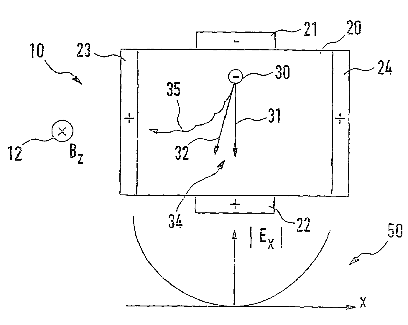
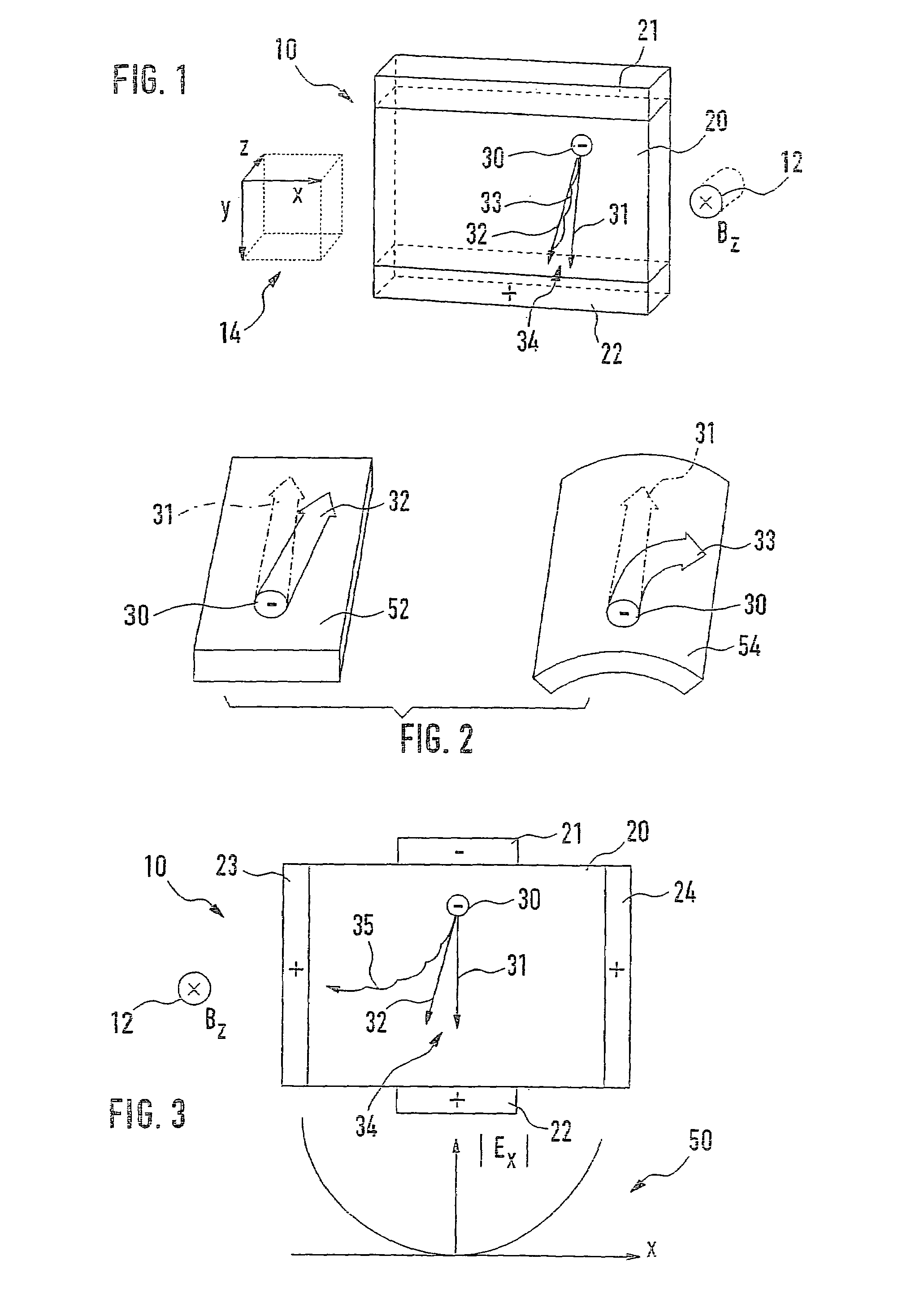
[0023]Set-up 10 is again represented in FIG. 3, but this time, in accordance with the present invention. Inside region 20, in the lateral direction, i.e. in the x direction, a field distribution 50 of a first electric field along the x direction is shown in the lower area of FIG. 3. Field distribution 50 indicates the magnitude of the components in the x direction of the first electric field. The first electric field is not explicitly shown in FIG. 3. It is apparent that, starting out from the center of region 20, the magnitude of the x component of the first electric field laterally increases, i.e. both in the positive and negative x directions.
[0024]This means that, initially, as soon as the switching-on of B component 12 of the magnetic field to be measured causes charge carrier 30 to no longer move along first movement direction 31 from first terminal 21 to second terminal 22, but laterally deflects it into second movement direction 32, so that deflection angle 34 is formed, at ...
second embodiment
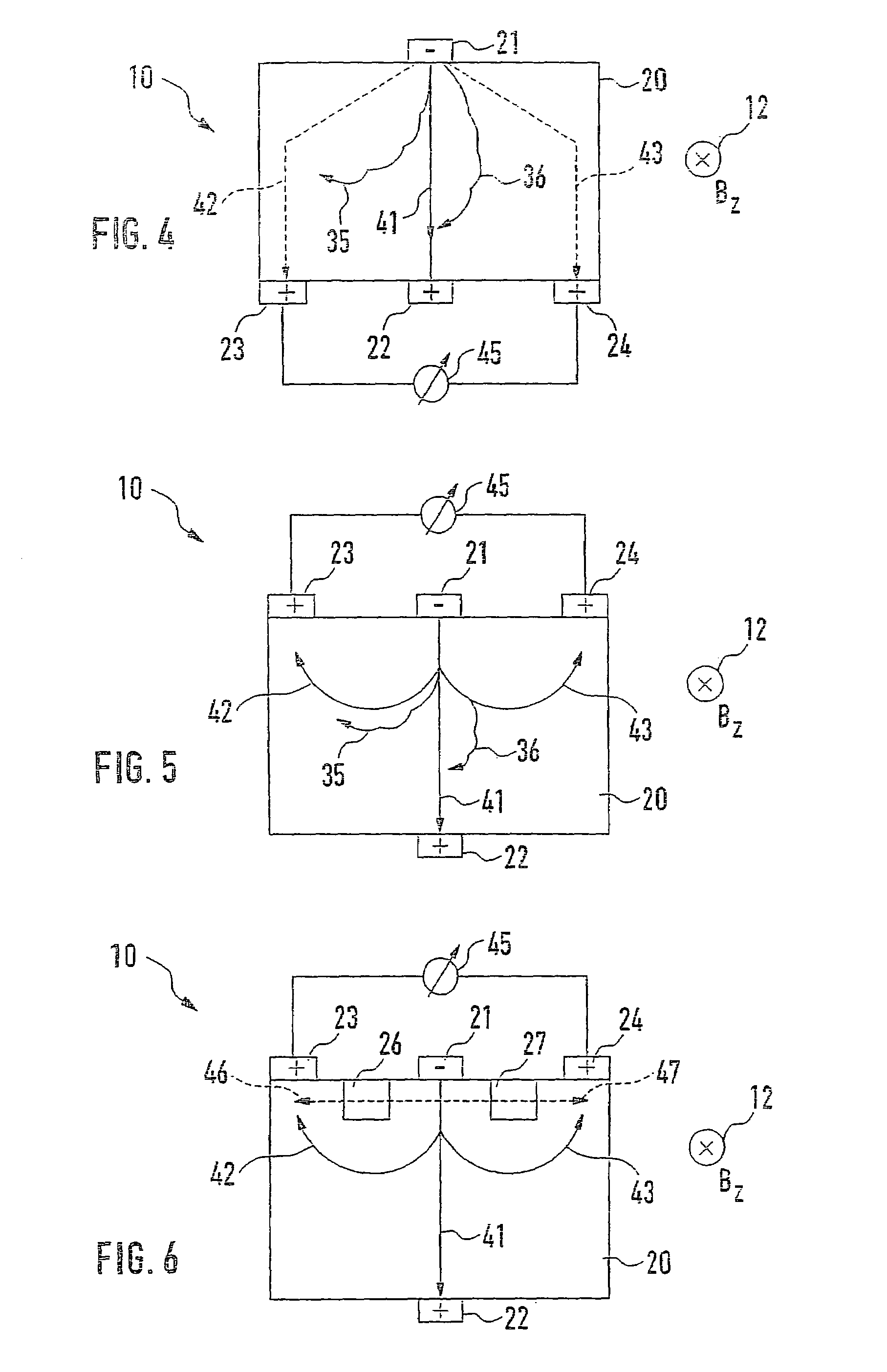
[0030]FIG. 4 shows device 10 according to the present invention. Identical designations from preceding figures correspond to the same parts, components, or directions. Once again, first terminal 21 is provided above region 20, essentially in the center in the x direction, while second terminal 22 is provided in the center of the lower side of region 20. In the specific embodiment of the device according to the present invention, electrodes 23 and 24 are provided on the lower side as well, but to the side of second terminal 22. Located between them is a voltage-measuring instrument 45, which allows the measuring signal of device 10 according to the present invention to be tapped off.
[0031]Also provided in FIG. 4 is a first current path 41, which is essentially the only one used by charge carriers 30 not shown, which arrive in region 20 from first terminal 21 when B component 12 is absent or disappears. In addition, a second current path 42 from first terminal 21 to first electrode 23...
PUM
 Abstract
Description
Claims
Application Information
 - R&D
- Intellectual Property
- Life Sciences
- Materials
- Tech Scout
- Unparalleled Data Quality
- Higher Quality Content
- 60% Fewer Hallucinations
Browse by: Latest US Patents, China's latest patents, Technical Efficacy Thesaurus, Application Domain, Technology Topic, Popular Technical Reports.
© 2025 PatSnap. All rights reserved.Legal|Privacy policy|Modern Slavery Act Transparency Statement|Sitemap|About US| Contact US: help@patsnap.com


