System and method for communicating data in a loadbalancing environment

a loadbalancing environment and data communication technology, applied in the field of communication, can solve the problems requiring additional work, and achieve the effects of reducing the number of central processing unit (cpu) cycles, facilitating communication, and increasing bandwidth

Active Publication Date: 2007-03-13
CISCO TECH INC
View PDF10 Cites 25 Cited by
  • Summary
  • Abstract
  • Description
  • Claims
  • Application Information

AI Technical Summary

Benefits of technology

[0006]Certain embodiments of the present invention may provide a number of technical advantages. For example, according to one embodiment of the present invention a communications approach is provided that allows a loadbalancer to only be actively involved in the initiation of a communication session. This reduction in responsibility for the loadbalancer operates to increase throughput as two points or nodes may efficiently communicate directly instead of having to direct all information through the loadbalancer for processing. This may further reduce the number of central processing unit (CPU) cycles that may be intensive and require additional work to be performed by the loadbalancer. Accordingly, the loadbalancer may be relegated to simple information transfer involving signaling and not be positioned in the path of data communications in order to inspect or evaluate information. The removal of the loadbalancer from the data transfer interaction between two nodes may further alleviate responsibilities designated for the loadbalancer such that greater bandwidth may be accommodated for in the network.
[0007]Yet another technical advantage of one embodiment of the present invention is also a result of the routing of data around the loadbalancer. The decreased reliance on the loadbalancer operates to better allocate network resources because per-tunnel state information is no longer needed to be maintained by the loadbalancer. In addition, the decreased dependency on the loadbalancer allows for improved failover characteristics such that, if the loadbalancer would become dysfunctional or non-operational, associated communication sessions may not necessarily be lost. Furthermore, redundancy problems are less challenging because of the reduction in duties assigned to the loadbalancer.
[0008]Still another technical advantage of one embodiment of the present invention relates to the configuration for communicating data in a loadbalancing environment. The configuration employed is simplified in accordance with the teachings of the present invention. This is a result of a signaling protocol being established in one location and a data exchange transfer being established in another location. The bifurcation of these two segments enhances data traffic management capabilities and further offers increased scalability as a result of the decreased processing responsibilities relegated to the loadbalancer. Certain embodiments of the present invention may enjoy some, all, or none of these advantages. Other technical advantages may be readily apparent to one skilled in the art from the following figures, description, and claims.

Problems solved by technology

This may further reduce the number of central processing unit (CPU) cycles that may be intensive and require additional work to be performed by the loadbalancer.

Method used


Image

  • System and method for communicating data in a loadbalancing environment
  • System and method for communicating data in a loadbalancing environment
  • System and method for communicating data in a loadbalancing environment

Examples


Embodiment Construction

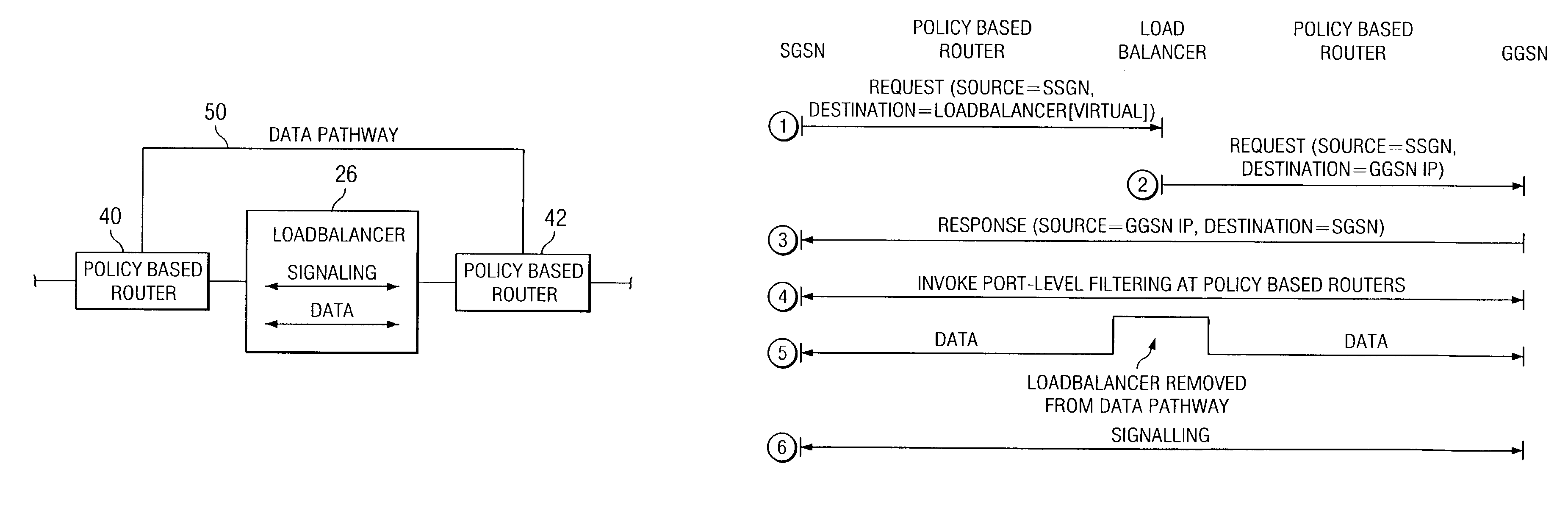
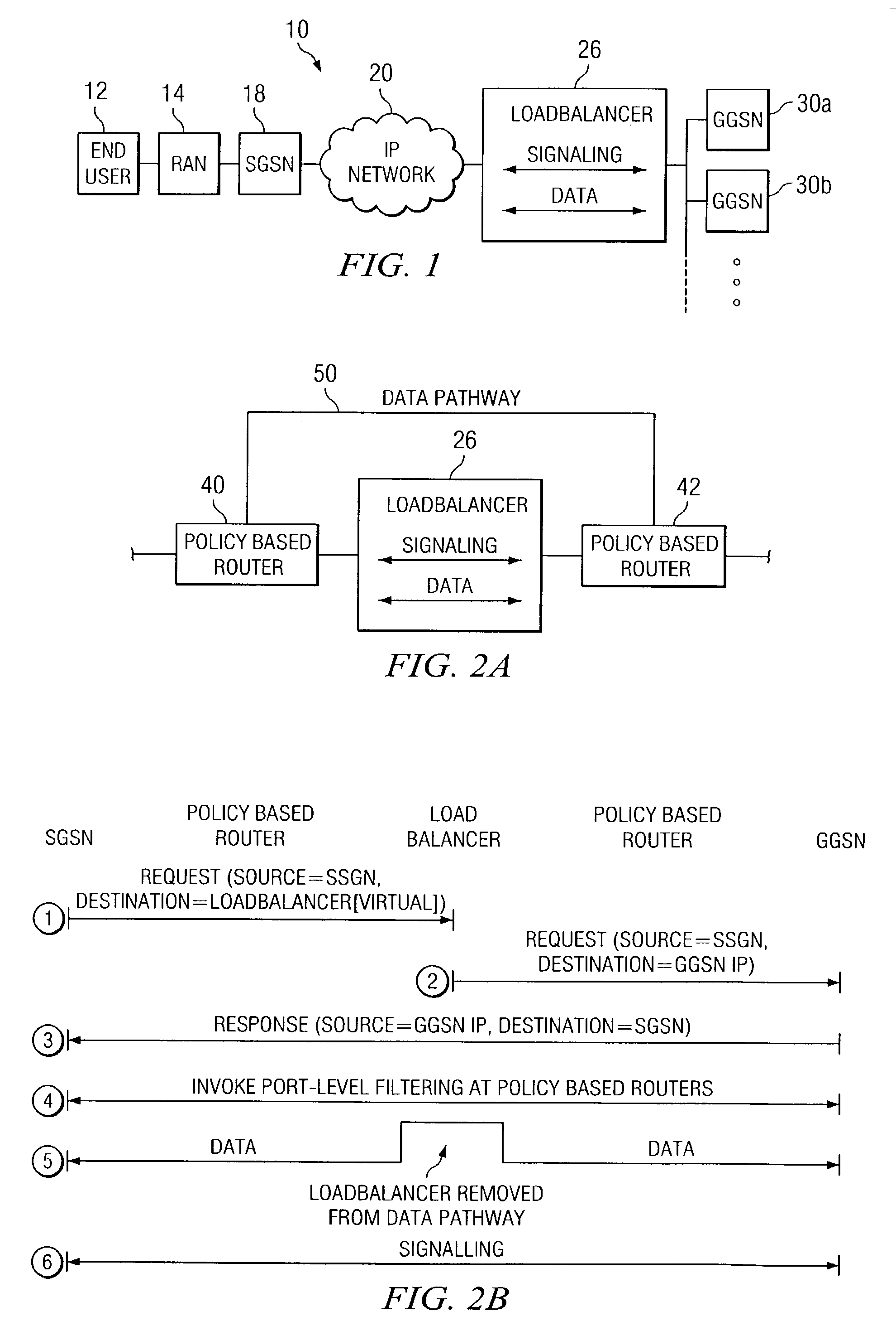
[0014]FIG. 1 is a simplified block diagram of a communication system 10 for communicating data in a network environment. Communication system 10 includes an end user 12, a radio access network (RAN) 14, a serving general packet radio service (GPRS) support node (SGSN) 18, and an internet protocol (IP) network 20. Additionally, communication system 10 includes a loadbalancer 26 and multiple gateway GPRS support nodes (GGSNs) 30a–b. FIG. 1 may be generally configured or arranged to represent a 2.5 G communication architecture applicable to a Global System for Mobile (GSM) environment in accordance with a particular embodiment of the present invention. However, the 2.5 G architecture is offered for purposes of example only and may alternatively be substituted with any suitable networking protocol or arrangement that provides a communicative platform for communication system 10. For example, communication system 10 may cooperate with any version of a GPRS tunneling protocol (GTP) that i...


PUM


Abstract

A method for communicating data in a network environment is provided that includes receiving a request from an end user for a communications link, the request being used to initiate a communication session. A response is then received that is communicated to the end user in order to establish the communication session, the response being generated by a network node that was selected as a result of a loadbalancing decision. Port-level filtering for the communication session may then be invoked after the response such that separate data and signal pathways are established for selected information associated with the communication session.

Description

TECHNICAL FIELD OF THE INVENTION[0001]This invention relates in general to the field of communications and more particularly to a system and method for communicating data in a loadbalancing environment.BACKGROUND OF THE INVENTION[0002]Networking architectures have grown increasingly complex in communications environments. In addition, the augmentation of clients or end users wishing to communicate in a network environment has caused many networking configurations and systems to respond by adding elements to accommodate the increase in networking traffic. Communication tunnels may be used in order to establish or to gain access to a network whereby an end user or an object may initiate a tunneling protocol by invoking a selected location or a network node. The network node or central location may then provide a platform that the end user may use to conduct a communication session.[0003]As the subscriber base of end users increases, proper routing and efficient management of communica...

Claims


Application Information

Patent Timeline
Patent Type & Authority Patents(United States)
IPC IPC(8): G06F15/16
CPCH04W28/08H04L67/1002H04W76/02H04W76/10H04L67/1001H04W28/088
Inventor O'ROURKE, CHRISCHANDWADKAR, ASHISH A.
Owner CISCO TECH INC
Why Eureka
Try Eureka