Methods and apparatus for correcting data and error detection codes on the fly

a technology of error detection codes and methods, applied in the field of methods and apparatus for correcting data and error detection codes on the fly, can solve problems such as the inability of the crc algorithm to readily correct errors

Inactive Publication Date: 2007-03-13
TOSHIBA STORAGE DEVICE CORP
View PDF4 Cites 82 Cited by
  • Summary
  • Abstract
  • Description
  • Claims
  • Application Information

AI Technical Summary

Benefits of technology

[0015]The ECC algorithm is executed on the first sector while a second sector is being read from the disk, to speed operation of the drive. When errors are found, both the data and the CRC value indicating the errors are corrected, without re-reading the first sector, even if the data is organized in symbols having one bit length and the ECC algorithm operates on the basis of symbols having a different symbol size. In one embodiment, the ECC algorithm generates ECC mask data that identifies the locations of the erroneous data. The erroneous data is corrected by performing an exclusive OR (XOR) operation on the erroneous data segments and the mask data. A CRC mask value is also generated from the ECC mask. The CRC mask value has the same number of bits as the first CRC value, but this time the CRC algorithm is executed on the basis of the symbol size of the ECC algorithm. An XOR operation is performed on the CRC value obtained from the erroneous data and the CRC mask value obtained from the ECC mask, which produces a correct CRC value for the corrected data. The correct CRC values are then stored in the volatile memory with the corrected data. When the data is read from the SDRAM and sent to the host, the CRC algorithm uses the data and stored CRC value to validate that the data has no errors.

Problems solved by technology

The stored CRC values can be used later to identify that errors have occurred, but the CRC algorithm cannot readily correct the errors.

Method used


Image

  • Methods and apparatus for correcting data and error detection codes on the fly
  • Methods and apparatus for correcting data and error detection codes on the fly
  • Methods and apparatus for correcting data and error detection codes on the fly

Examples


Embodiment Construction

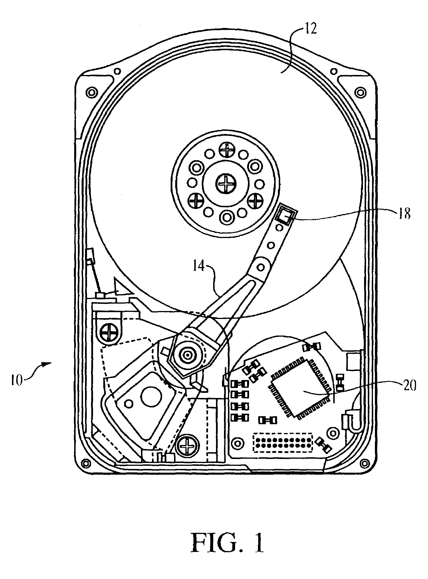
[0033]As seen in FIG. 1, a typical magnetic disk drive 10 includes a magnetic disk 12, a spindle motor (not shown) that rotates the disk at a desired speed, and a head arm 14 that pivots to move a recording / reproducing head 18 back and forth across the disk as the disk rotates. The head 18 can have a single head for both reading and writing, or separate heads for reading and writing. A controller 20 is also provided.

[0034]The magnetic disk drive 10 could also be an optical or magneto-optical drive or the like, a tape drive or the like, or simply a communication system. The disk 12 could be any suitable media, such as an optical or magneto-optical disk or the like, tape or the like, or a communication channel. These devices also have at least one head or the like, and a suitable controller.

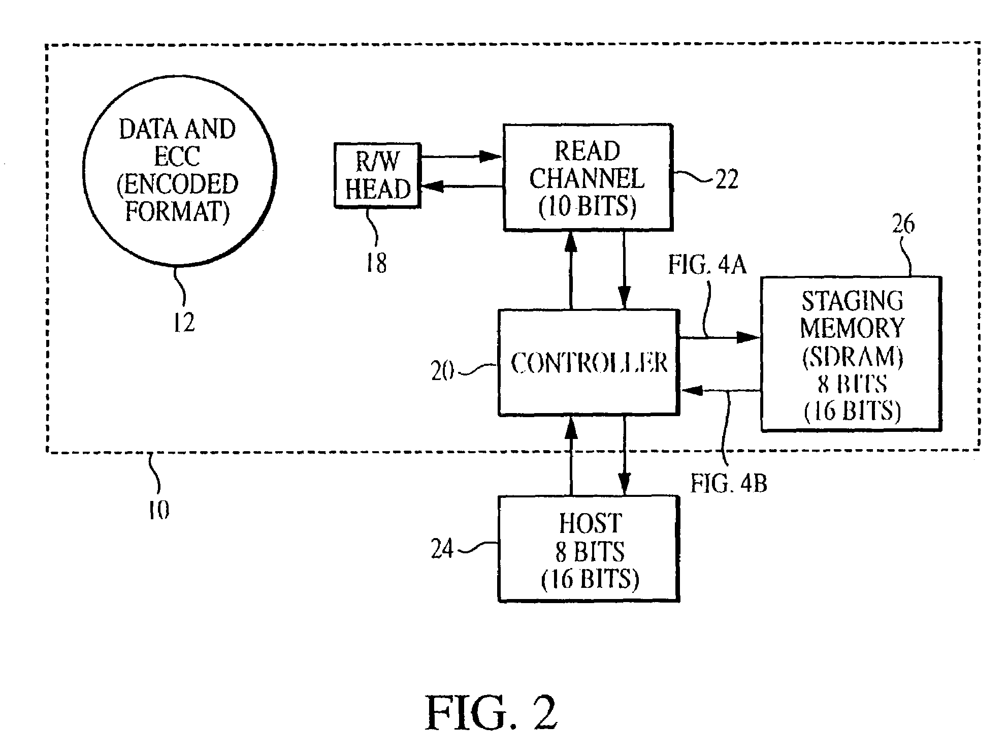
[0035]The head 18 writes data to and reads data from the disk 12 with the general circuit configuration shown in FIG. 2. The controller 20 controls the reading and writing operations of the head 18...


PUM

PropertyMeasurementUnit
lengthaaaaaaaaaa
bit lengthaaaaaaaaaa
volatileaaaaaaaaaa

Abstract

When data is read from a disk and stored in volatile memory, check bits are generated and stored in the memory using an algorithm such as cyclical redundancy check (CRC). The CRC algorithm operates on the basis of the bit length in which the data is organized, such as 8 bits. If the data has errors, an error correction code (ECC) algorithm is used to correct the data errors, but the ECC algorithm operates on the basis of symbols having a different bit length, such as 10 bits. To avoid having to re-read the data from the volatile memory to adjust the CRC value, the CRC algorithm is executed on selected mask data developed by the ECC algorithm, the CRC algorithm being executed on the basis of the second bit length to generate a CRC mask. The CRC mask corrects the stored CRC value.

Description

[0001]This invention relates to methods and apparatus for detecting and correcting data errors, and more particularly, to methods and apparatus for correcting data errors and data error detection codes such as cyclical redundancy check (CRC) values on the fly, without requiring re-reading of data.BACKGROUND OF THE INVENTION[0002]In modern computer systems, data is constantly written to and read front several memory devices. One such device is a disk drive. While disk drives are used for permanent or non-volatile data storage on a magnetic or optical disk, they typically use internal volatile memory such as SDRAM to stage data before writing data to the disk. The SDRAM is also used to stage data after reading it from the disk, before it is sent to the host. However, every staging operation in the SDRAM creates an opportunity for error, both from the host to the disk and from the disk to the host. As a result, some method of error detection (and sometimes correction) must be employed ...

Claims


Application Information

Patent Timeline
Patent Type & Authority Patents(United States)
IPC IPC(8): G11C29/00G11B20/18H03M13/15H04B1/74
CPCG11B20/1833H03M13/093H03M13/091
Inventor JAMES, MICHAELONO, KANA
Owner TOSHIBA STORAGE DEVICE CORP
Why Eureka
Try Eureka