Device and method for transferring force to a targeted objected

a technology of target objects and devices, applied in the field of sliding hammers, can solve the problems of less uniform angle at which force is applied to a targeted object, more difficult to maintain alignment of path, and easy to grip during use, so as to reduce the shock of impact, increase or decrease the amount of force, and reduce the effect of impact shock

Inactive Publication Date: 2007-03-20
SLIDE SLEDGE
View PDF32 Cites 29 Cited by
  • Summary
  • Abstract
  • Description
  • Claims
  • Application Information

AI Technical Summary

Benefits of technology

[0008]In its simplest form, the slide hammer of this invention is a hammering device which allows the force of an impact to be transferred to a targeted object. The apparatus has three major components, namely, a guide sleeve, a plunger, and an impact head. The plunger is inserted within the guide sleeve. The impact head is secured within the distal end of the guide sleeve, and has a portion which protrudes from the guide sleeve distal end. In one configuration, the impact head is able to freely slide within a specified portion of the guide sleeve distal end. In another configuration, a spring can be used to stabilize the impact head within the guide sleeve. The plunger is slid within the guide sleeve and is able to make contact with the portion of the impact head slidably secured within the guide sleeve. The force of the plunger striking the impact head is transmitted through the impact head to a targeted object contacted by the impact head, such as a vehicle frame member. The impact head may be fitted with various types

Problems solved by technology

With a hammer and chisel, it is much more difficult to maintain this aligned path between the chisel axis and the angle at which the hammer strikes the chisel head; therefore, the angle at which force is applied to a targeted object is more inconsistent.
The advantage of using a spring within the impa

Method used


Image

  • Device and method for transferring force to a targeted objected
  • Device and method for transferring force to a targeted objected
  • Device and method for transferring force to a targeted objected

Examples


first embodiment

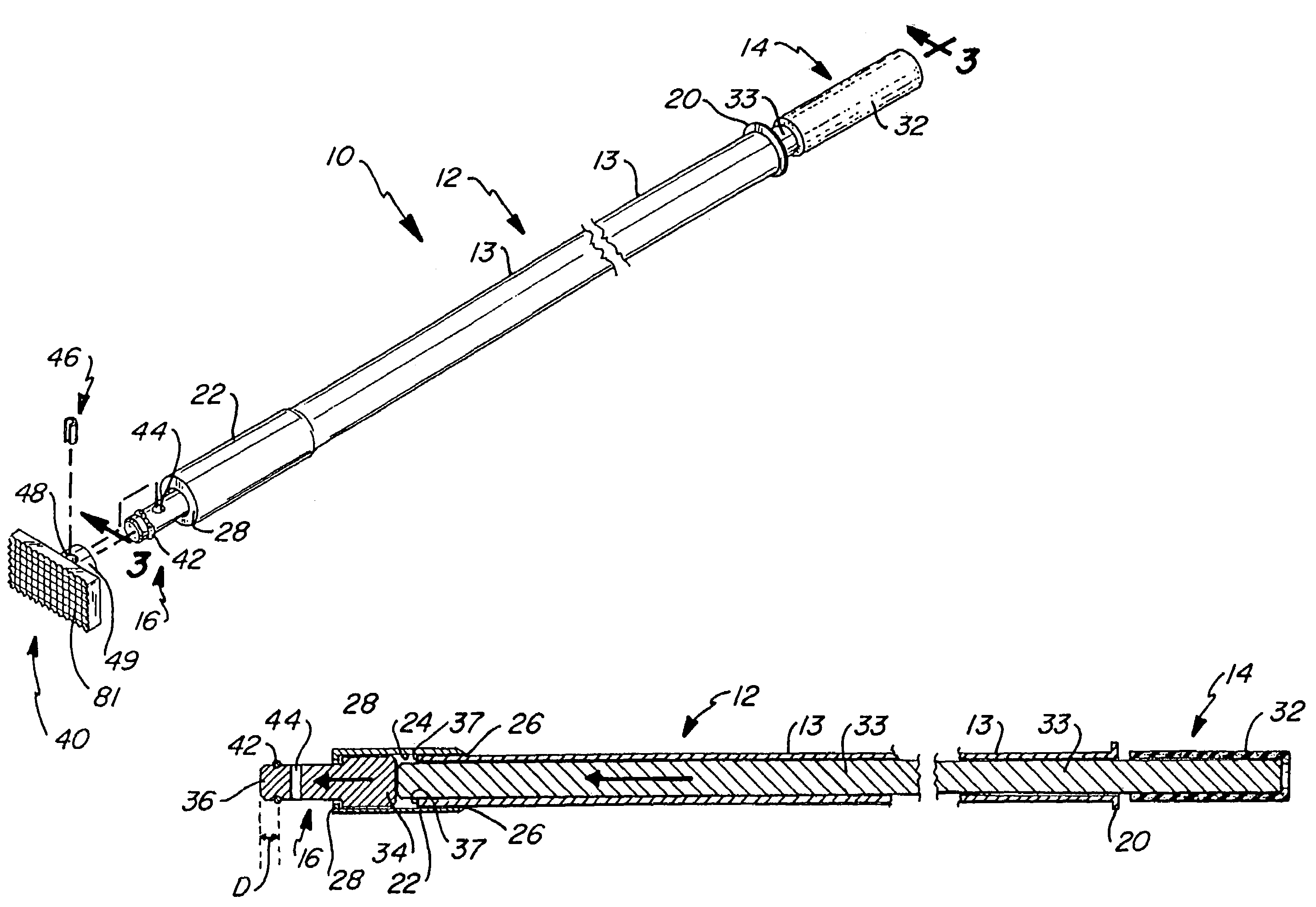
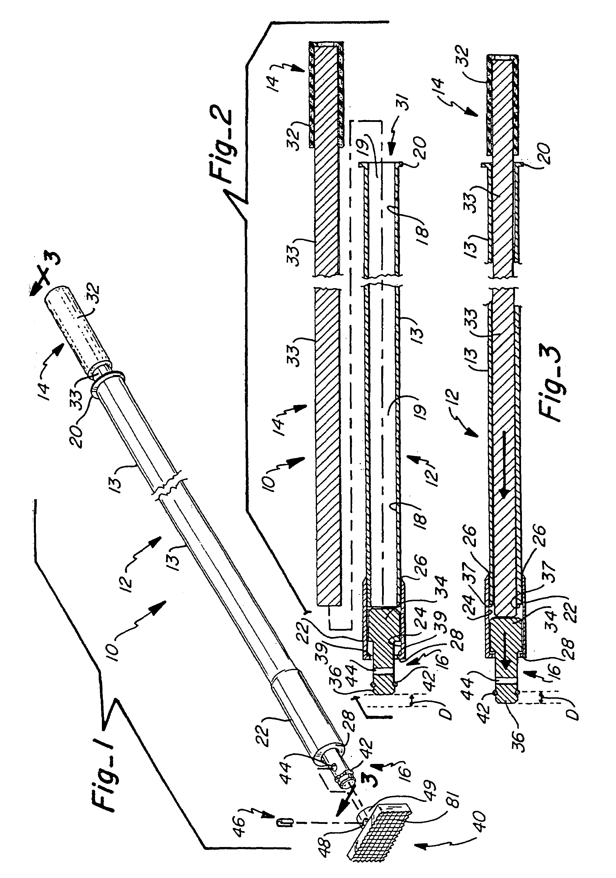
[0040]As shown in FIGS. 1–3 in a first embodiment, the slide hammer 10 includes three major components, namely, a guide sleeve 12, a plunger 14 that is slidably engaged within said guide sleeve, and an impact head 16 which is slidably secured within the distal end of the guide sleeve 12. The guide sleeve 12 is preferably of a cylindrical shape, and has a main guide sleeve section 13 and a corresponding inner cylindrical surface 18 forming a longitudinal passageway 19. A flange 20 is formed at the proximal end of the guide sleeve. The guide sleeve 12 further includes an impact head receiving section 22. As shown in the vertical sections of FIGS. 2 and 3, receiving section 22 has an inner cylindrical surface 24 which is of a slightly larger diameter than inner surface 18. Receiving section 22 may simply be a larger sized cylinder pipe member which overlaps with main guide sleeve section 13 at welded joint or overlap area 26. The distal end of head receiving section 22 has a washer or ...

second embodiment

[0053]Now referring to FIGS. 9 and 14–16, the second embodiment also includes a removable end cap 310 which is threadably received on the proximal end of the guide sleeve. A handle 312 of a rubber or resilient type of material may be attached to the proximal end of the plunger to facilitate grasping by the user. Additionally, the proximal end of the plunger may include a threaded extension 314 which may be used to attach a desired weight 316 thereto. Referring specifically now to FIG. 15, the end cap 310 is shown. It includes a plurality of internal threads 318, a flange 320, and an inner concentric extension or flange 322. A resilient cover 315 (FIG. 8) may be placed over the exposed threads 314 when a weight 316 is not used. As seen in FIG. 16, when the plunger is nearly completely withdrawn from the guide sleeve, a split ring 324 attached to the plunger prevents the plunger from being removed from the guide sleeve as the split ring contacts the smaller diameter portion formed by ...


PUM

PropertyMeasurementUnit
Forceaaaaaaaaaa
Speedaaaaaaaaaa

Abstract

A slide hammer includes three major components, namely, a guide sleeve, a plunger and an impact head. The plunger is inserted within the guide sleeve. The impact head is secured within the distal end of the guide sleeve, and has a portion which protrudes from the guide sleeve distal end. The impact head is able to freely slide within a segmented portion of the guide sleeve distal end, or the impact head movement may be controlled by a spring. The plunger is slid within the guide sleeve at a selected velocity in order to contact the portion of the impact head slidably secured within the guide sleeve. The force of the plunger striking the impact head is transmitted through the impact head to a targeted object in contact with the protruding portion of the impact head. The impact head may be fitted with various types of tips. Each of the tips has particular advantages in applying force to a targeted object.

Description

CROSS REFERENCE TO RELATED APPLICATIONS[0001]The present application is a continuation of U.S. patent application Ser. No. 10 / 192,544, filed Jul. 9, 2002 now abandoned, entitled “SLIDE HAMMER”, which is incorporated herein by this reference.[0002]This application is a continuation-in-part application of U.S. Ser. No. 10 / 013,411 filed on Dec. 7, 2001 now U.S. Pat. No. 6,474,198 entitled “SLIDE HAMMER”, which is a continuation-in-part application of U.S. Ser. No. 09 / 677,497, filed Oct. 2, 2000, entitled “SLIDE HAMMER”, now U.S. Pat. No. 6,349,618, which is a Continuation-in-Part application of U.S. Ser. No. 09 / 281,007, filed Mar. 30, 1999, entitled “SLIDE HAMMER”, now U.S. Pat. No. 6,125,719.TECHNICAL FIELD[0003]This invention relates to a device which transfers the force of an impact to a targeted object and, more particularly, to a slide hammer which transfers the force of an impact to a targeted object.BACKGROUND OF THE INVENTION[0004]It is known to use various combinations of chis...

Claims


Application Information

Patent Timeline
IPC IPC(8): B25D1/00B21D1/06B25B27/02B25D1/16
CPCB21D1/06B25D1/16B25B27/02
Inventor LOWTHER, JOHN K.
Owner SLIDE SLEDGE
Why Eureka
Try Eureka