
Damper mechanism and damper disk assembly

Inactive Publication Date: 2007-03-20
EXEDY CORP
View PDF6 Cites 8 Cited by
  • Summary
  • Abstract
  • Description
  • Claims
  • Application Information

AI Technical Summary

Benefits of technology

[0011]An object of the present invention is to provide a simple structure in a damper mechanism, which absorbs and attenuates minute torsional vibration during idling.
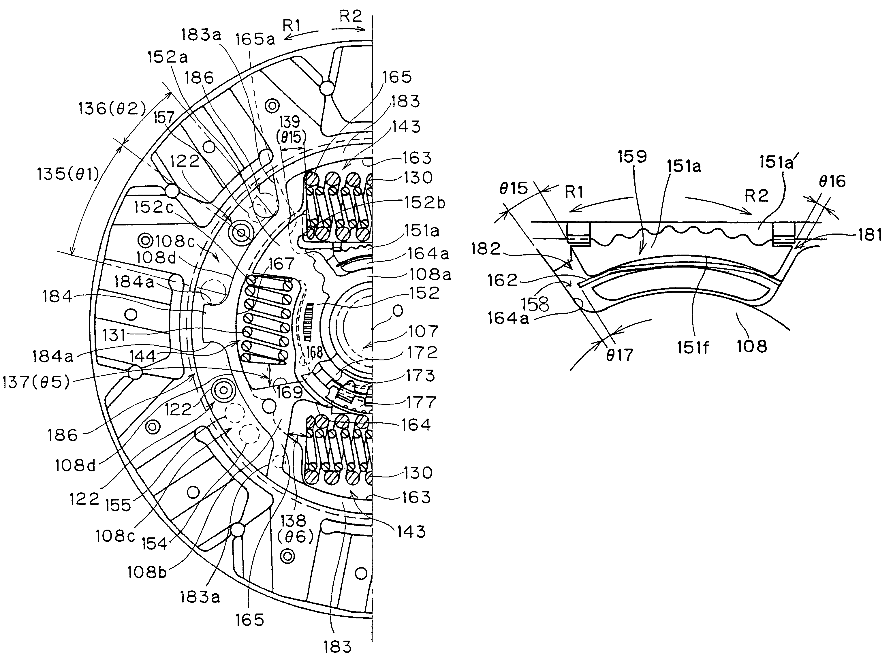
[0013]In this damper mechanism, when minute torsional vibrations are input to the damper disk assembly during idling, the first rotating member and the second rotating member rotate relative to each other. Thus, the plate member is pushed by the first rotating member and slides against the second rotating member, thereby generating frictional resistance. As a result, the minute torsional vibrations are quickly dampened. Use of the plate member simplifies the damper mechanism structure and decreases the number of parts.
[0017]A damper mechanism in accordance with a fifth aspect of the present invention is the damper mechanism of the fourth aspect, wherein the rotation direction length between the pair of contact portions is preferably longer than the rotational direction length of the plate member, so that a rotational direction gap is secured at least between one of the ends of the plate member and one of the contact portions. In this damper mechanism, within the rotational direction gap the plate member does not slide against the second rotating member while the first rotating member and the second rotating member rotate relative to each other because the rotational gap is secured at least between one of the ends of the plate member and one of the contact portions. In other words, even in the torsional angular range by the first rotating member and the second rotating member, minute torsional vibrations corresponding to the rotational direction gap do not cause friction resistance. As a result, minute torsional vibration dampening performance is improved.
[0020]In this damper disk assembly, when minute torsional vibrations are input to the damper disk assembly during idling, the hub and the intermediate rotating member rotate relative to each other. Thus, the plate member is pushed by the hub and slides against the intermediate rotating member, thereby generating frictional resistance. As a result, the minute torsional vibration is quickly dampened. The plate member makes the damper mechanism simpler, decreasing the number of parts.
[0024]A damper disk assembly of the eleventh aspect is the damper disk assembly of the tenth aspect, wherein the rotational direction length between the pair of contact portions is preferably longer than the rotational direction length of the plate member, so that a rotational direction gap is secured at least between one of the rotational ends of the plate member and one of the contact portions. In this damper disk assembly, the plate member does not slide against the intermediate rotating member within the rotational gap while the hub and the intermediate rotating member rotate relative to each other because the rotational gap is secured at least between on of the ends of the plate member and one of the contact portions. In other words, even in the torsional angular range of the hub and the intermediate rotating member, minute torsional vibrations corresponding to the rotational gap do not cause frictional resistance. As a result, minute torsional vibration dampening performance is improved.

Problems solved by technology

As a result, the minute torsional vibrations are quickly dampened.

Method used


Image

  • Damper mechanism and damper disk assembly
  • Damper mechanism and damper disk assembly
  • Damper mechanism and damper disk assembly

Examples


Embodiment Construction

[0046]Selected embodiments of the present invention will now be explained with reference to the drawings. It will be apparent to those skilled in the art from this disclosure that the following descriptions of the embodiments of the present invention are provided for illustration only and not for the purpose of limiting the invention as defined by the appended claims and their equivalents.

[0047]A preferred embodiment will now be explained.

(1) Overall Constitution

[0048]

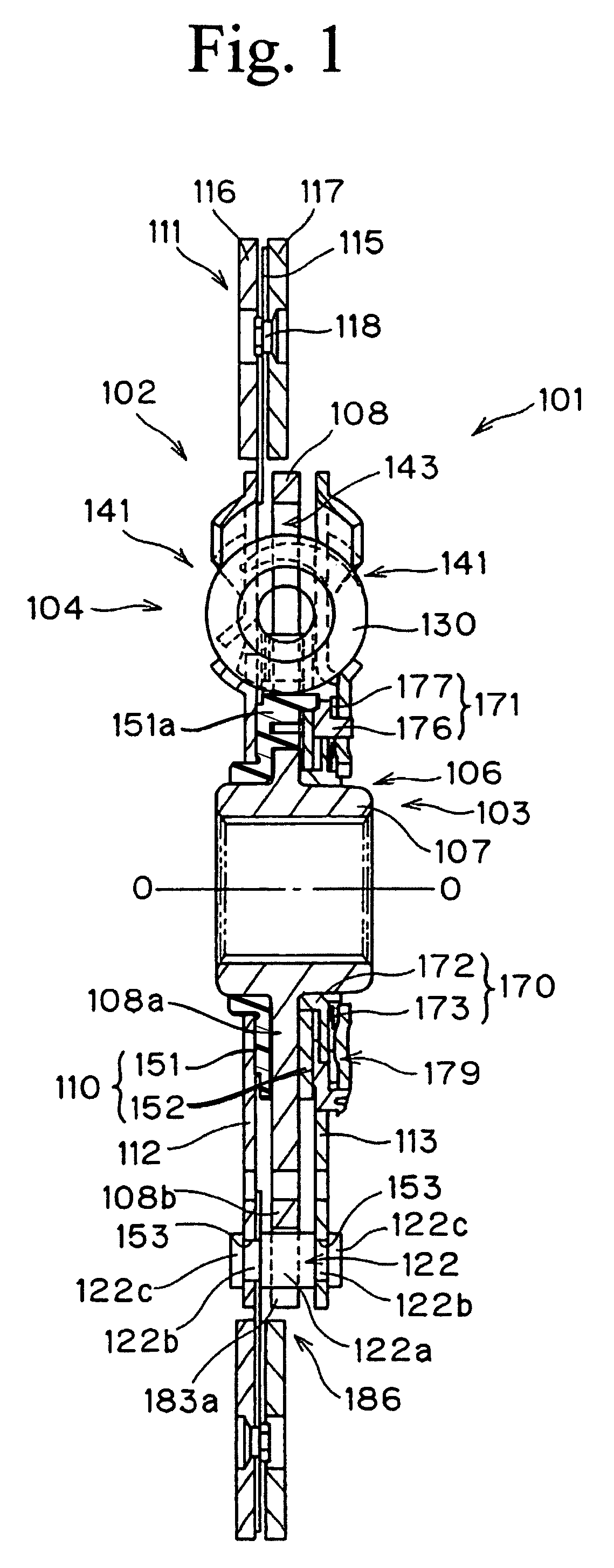
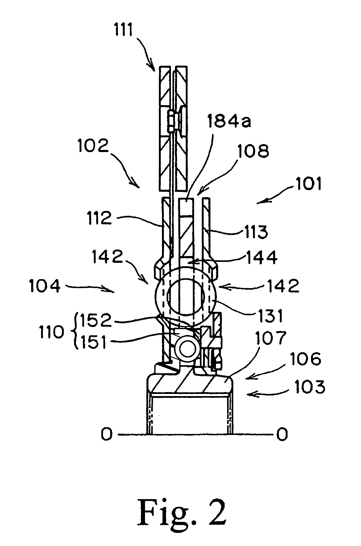
[0049]FIG. 1 and FIG. 2 are cross-sectional views of a clutch disk assembly 101 in accordance with a preferred embodiment of the present invention, and FIG. 3 is an elevational view of the same. The clutch disk assembly 101 is a power-transmitting device used in a clutch device of a vehicle (especially a FF, front engine and front drive, car), and has a clutch function and a damper function. The clutch function is provided to transmit and interrupt power by connecting and disconnecting with a flywheel (not shown). The ...


PUM


Abstract

A first damper mechanism 159 for absorbing and attenuating minute torsional vibration in a damper disk assembly for transmitting torque in a vehicle, has a plate spring 162. The plate spring 162 extends in the rotational direction having main surfaces facing in the radial direction. The plate spring 162 is pushed by the hub 106 in the rotational direction to slide against the intermediate rotating member 110 when the hub 106 and the intermediate rotating member 108 rotate relative to each other, thereby generating friction resistance.

Description

CROSS-REFERENCE TO RELATED APPLICATIONS[0001]This application is related to previously application Ser. No. 10 / 437,007, filed May 14, 2003, now U.S. Pat. No. 6,837,354 patented Jan. 4, 2005, commonly assigned with the present invention.BACKGROUND OF THE INVENTION[0002]1. Field of the Invention[0003]The present invention generally relates to a damper mechanism and a damper disk assembly. More specifically, the present invention relates to a damper mechanism and a damper disk assembly for absorbing and attenuating torsional vibrations while transmitting torque.[0004]2. Background Information[0005]A clutch disk assembly used in a vehicle has a clutch function and damper function. The clutch function is provided to facilitate connecting to and disconnecting from a flywheel. The damper function is provided to facilitate absorbing and attenuating torsional vibrations transmitted from the flywheel. Generally speaking, vibrations on a vehicle include idling noises (rattling), driving noises...

Claims


Application Information

Patent Timeline
IPC IPC(8): F16F15/129F16D13/46F16D13/64
CPCF16F15/1292
Inventor UEHARA, HIROSHI
Owner EXEDY CORP
Learn More