
Control apparatus and method for automotive vehicle in which a belt-type continuously variable transmission is equipped with a belt slip preventive feature

a technology of continuously variable transmission and control apparatus, which is applied in the direction of electric control, gearing control, gearing elements, etc., can solve the problems of insufficient supply of clamp pressure for the belt, sticky valve constituting the electromagnetic hydraulic control valve, and lowering line pressure, so as to improve the durability of the belt and reduce the line pressure

Inactive Publication Date: 2007-03-20
JATCO LTD +1
View PDF13 Cites 22 Cited by
  • Summary
  • Abstract
  • Description
  • Claims
  • Application Information

AI Technical Summary

Benefits of technology

[0006]It is, therefore, an object of the present invention to provide control apparatus and method for the belt continuously variable transmission associated with an engine which are capable of preventing the occurrence of the belt slip and improving the durability of the belt even if the waste or dust is invaded into the hydraulic circuit to reduce the line pressure.

Problems solved by technology

However, if a (waste or dust) is invaded into a hydraulic circuit disclosed in the above-described Japanese Patent Application Publication, the valve constituting the electromagnetic hydraulic control valve becomes sticky due to a clogging of the waste or dust so that the line pressure becomes lowered.
If the line pressure is lowered, the clamp pressure for the belt is not sufficiently supplied.
Thus, a slip of the belt occurs.
On the contrary, there is a possibility that the belt slips when an engine speed is slow and the line pressure becomes lowered.

Method used


Image

  • Control apparatus and method for automotive vehicle in which a belt-type continuously variable transmission is equipped with a belt slip preventive feature
  • Control apparatus and method for automotive vehicle in which a belt-type continuously variable transmission is equipped with a belt slip preventive feature
  • Control apparatus and method for automotive vehicle in which a belt-type continuously variable transmission is equipped with a belt slip preventive feature

Examples


first embodiment

[0018](First Embodiment)

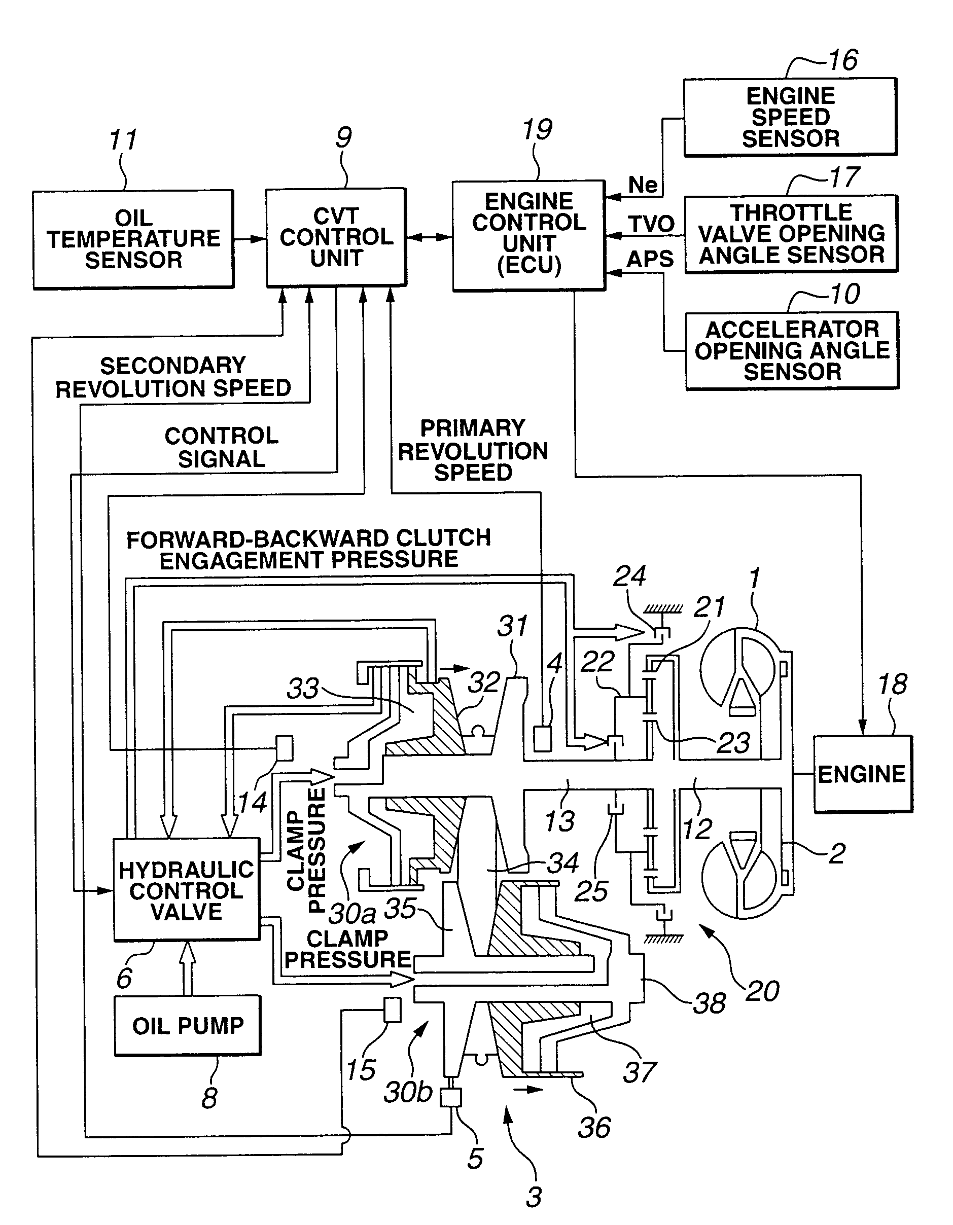
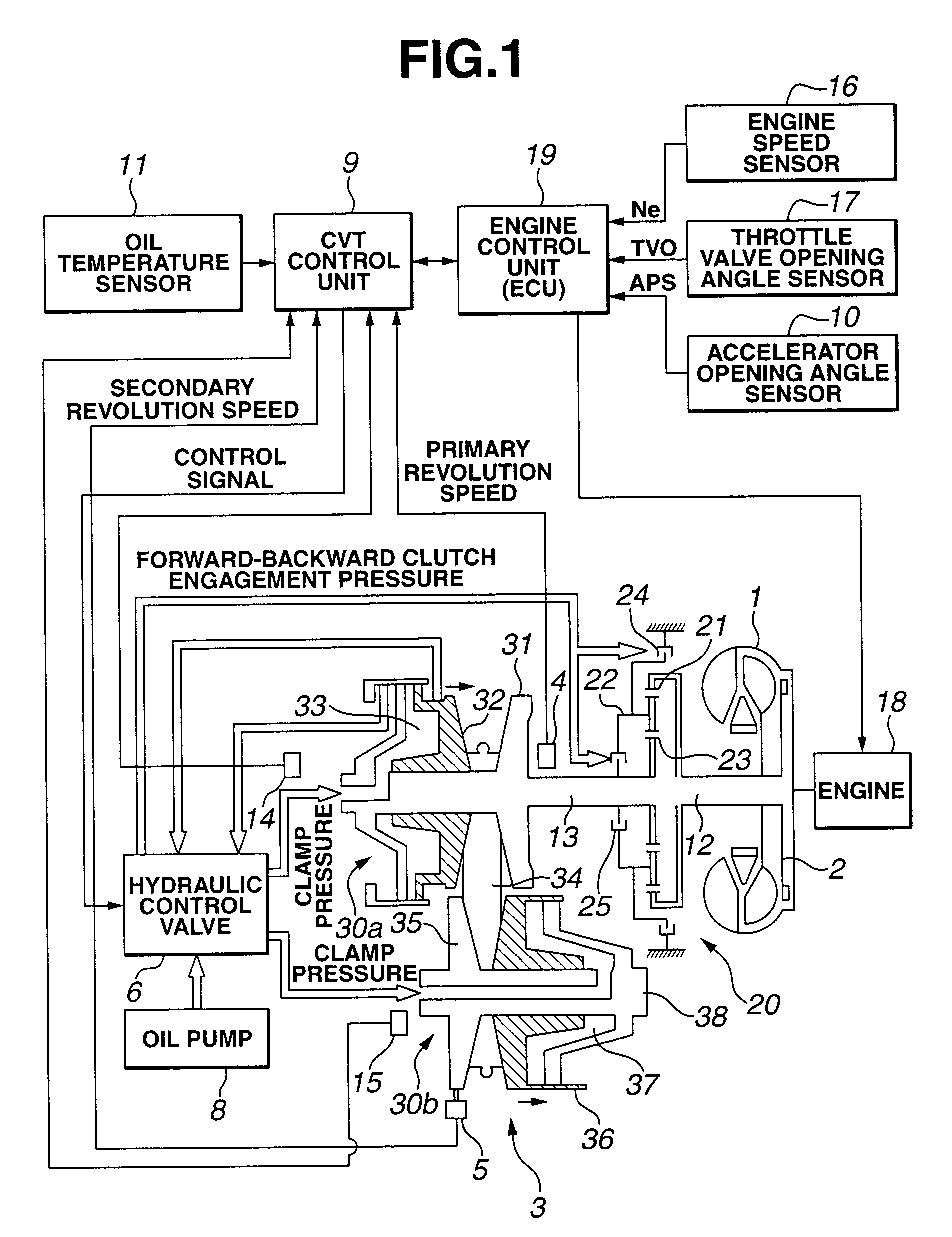
[0019]FIG. 1 shows a control system of an engine and a belt(-type) continuously variable transmission 3 (hereinafter, described as CVT) to which a first preferred embodiment of a control apparatus according to the present invention is applicable.

[0020]Reference numeral 1 denotes a torque converter, reference numeral 2 denotes a lock-up clutch, reference numeral 3 denotes a CVT (Continuously Variable Transmission), reference numeral 4 denotes a primary pulley revolution speed sensor, reference numeral 5 denotes a secondary pulley revolution speed sensor, reference numeral 6 denotes a hydraulic control valve unit, reference numeral 8 denotes an oil pump driven with an engine, reference numeral 9 denotes a CVT control unit, reference numeral 10 denotes an accelerator opening angle sensor, reference numeral 11 denotes an oil temperature sensor, reference numeral 18 denotes an engine, reference numeral 19 denotes an engine control unit (hereinafter, also abbreviat...

second embodiment

[0038](Second Embodiment)

[0039]Next, a second preferred embodiment of the control apparatus will be described. A basic structure of the second embodiment is generally the same as described in the first embodiment. Hence, only a difference point will be described below. FIG. 5 shows an operational flowchart representing a belt slip preventive control when the belt slip is detected. Since steps S201 through S206 are the same as described in the first embodiment, different steps will be explained below. That is to say, at a step S301, CVT control unit 9 determines whether the velocity of the vehicle in which the control apparatus according to the present invention is mounted (VSP) is zero. If the vehicle is stopped (VSP=0), the routine goes to a step S302. If VSP≠0 at step S301 (No), the routine goes to step S201. The contents of step S201 has been described. At step S302, CVT control unit 9 determines whether a line pressure PL is larger than a predetermined line pressure PPL. If PL>P...

third embodiment

[0040](Third Embodiment)

[0041]Next, a third preferred embodiment of the control apparatus according to the present invention will be described. The basic structure of the third embodiment is generally the same or described in the first embodiment. Hence, the difference points will be described below. FIG. 6 shows an operational flowchart representing the belt slip preventive control when the belt slip is detected. Steps S201 through S206 are generally the same as those described in the first embodiment. The difference points will only be described below. At step S401, CVT control unit 9 determines if the vehicle speed VSP, viz., the vehicle is stopped.

[0042]At a step S402, CVT control unit 9 determines if line pressure PL is larger than a predetermined line pressure PPL. If PL>PPL (Yes) at step S402, the routine goes to a step S403. At step S403, a line pressure decrease flag f is set to “0”. At step S404, line pressure decrease flag f is set to “1”. At a step S405, CVT control unit...


PUM


Abstract

In control apparatus and method for an automotive vehicle, the vehicle having a continuously variable transmission associated with a vehicular engine and including a belt that transmits a revolution of a primary pulley to a secondary pulley that is enabled to make a gear shift by modifying a pulley ratio between the primary and secondary pulleys with a hydraulic, a determination is made as to whether a belt slip between at least one of the primary and the secondary pulleys occurs and an output section outputs a signal to command an engine control unit to increase an engine speed by a predetermined engine speed when the belt slip is determined to occur.

Description

BACKGROUND OF THE INVENTION[0001]1. Field of the Invention[0002]The present invention relates to shift hydraulic system of a belt-type continuously variable transmission. More particularly, the present invention relates to control apparatus and method for preventing an occurrence of a belt slip of the belt-type continuously variable transmission (so called, CVT).[0003]2. Description of the Related Art[0004]A Japanese Patent Application First Publication No. Heisei 9-250370 published on Sep. 22, 1997 exemplifies a previously proposed shift hydraulic system for a belt-type continuously variable transmission. In the above-described Japanese Patent Application First Publication, when an electromagnetic hydraulic control valve has failed to control a line pressure, a technique to prevent an excessive rise in the line pressure is disclosed. That is to say, if the electromagnetic hydraulic control valve has failed, the hydraulic valve becomes an open state such that the hydraulic of an oil...

Claims


Application Information

Patent Timeline
Patent Type & Authority Patents(United States)
IPC IPC(8): F16H61/662F02D45/00F02D29/00F02D29/02F16H59/16F16H59/26F16H59/42F16H59/68F16H59/74F16H61/04F16H61/12F16H63/06F16H63/50
CPCB60W10/06B60W10/107B60W30/188F16H61/66272F16H2312/14Y10T477/68Y10T477/62427Y10T477/6242Y10T477/679Y10T477/62429Y10T477/624Y10T477/6237F16H61/04
Inventor SHIMADA, TETSUYAIRIYAMA, MASAHIROGOTOU, KENICHIYAMAMOTO, MASAHIROKODAMA, YOSHIHISASHIMANAKA, SHIGEKITANAKA, HIROYASUINOUE, TAKUICHIROWAKAHARA, TATSUONOBU, HISAO
Owner JATCO LTD
Learn More