Methods and apparatus for driving a quadrupole ion trap device

a trap device and quadrupole ion technology, applied in mass spectrometers, isotope separation, particle separator tubes, etc., can solve the problems of increased instrument cost and complexity, unsatisfactory shift in the resonance position of the network, and limited voltage outpu

Inactive Publication Date: 2007-03-20
SHIMADZU RES LAB EURO
View PDF13 Cites 44 Cited by
  • Summary
  • Abstract
  • Description
  • Claims
  • Application Information

AI Technical Summary

Benefits of technology

[0009]According to one aspect of the invention there is provided a method for driving a quadrupole ion trap device including creating a digital signal, using the digital signal to control a set of switches to cause the switches alternately to switch between a high voltage level and a low voltage level to generate a time-varying rectangular wave voltage, supplying the time-varying rectangular wave voltage to

Problems solved by technology

Also, sometimes an undesirable shift in the resonance position of the network caused by a change in output voltage needs to be corrected.
These factors have resulted in increased costs and complexity of instruments.
This voltage output is limited by the power consumpt

Method used


Image

  • Methods and apparatus for driving a quadrupole ion trap device
  • Methods and apparatus for driving a quadrupole ion trap device
  • Methods and apparatus for driving a quadrupole ion trap device

Examples


Embodiment Construction

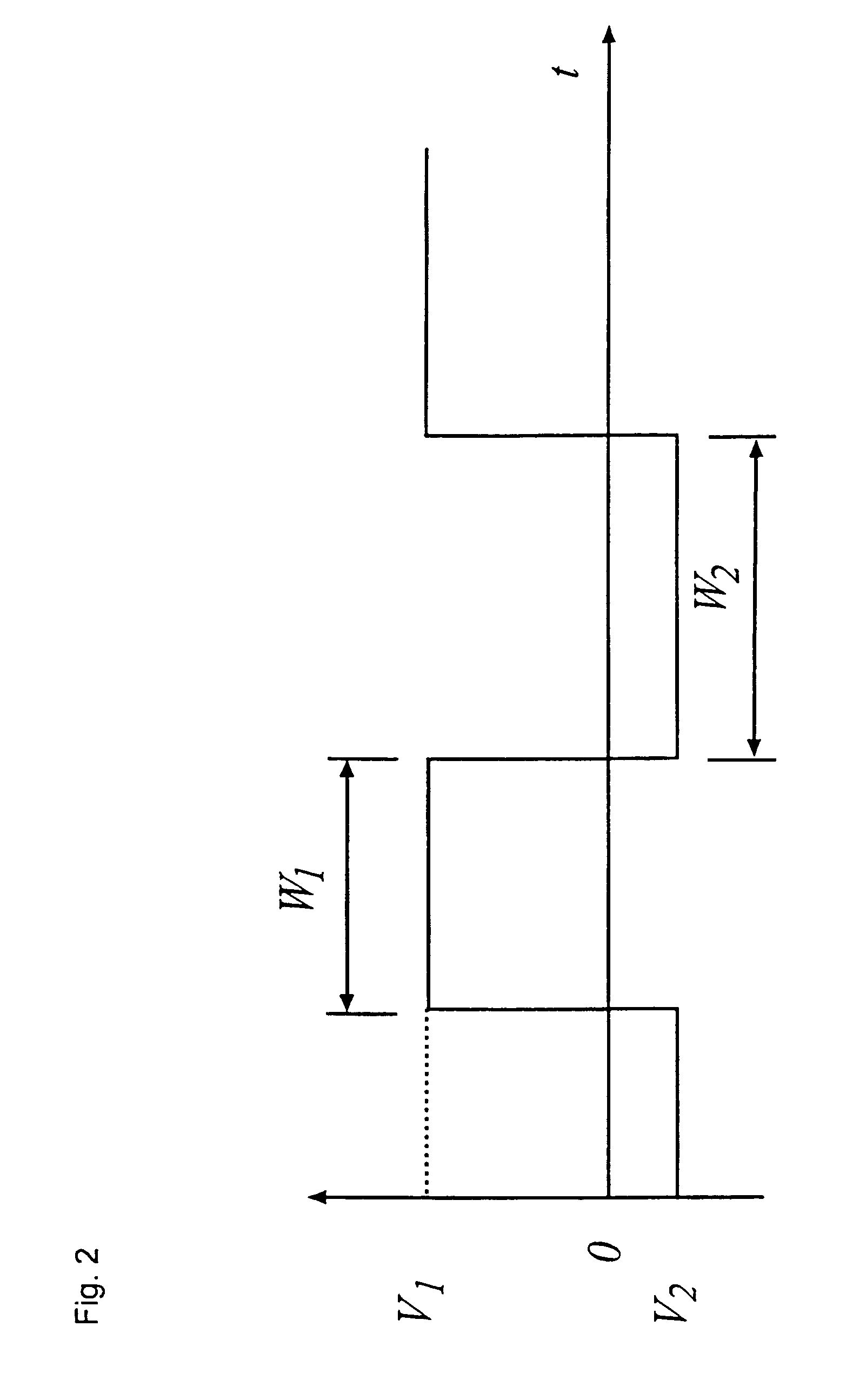
[0020]The rectangular wave voltage shown in FIG. 2 has a width w1 at a high voltage level V1 and a width w2 at a low voltage level V2. In this example, the rectangular wave voltage has a DC offset U given by:

U=(w1V1+w2V2) / (w1+w2)  (1)

and a repetition rate f given by:

f=(w1+w2)−1  (2)

[0021]FIG. 3a shows an example of a drive apparatus for generating the rectangular wave voltage of FIG. 2. The drive apparatus includes a clock 11 for generating a high frequency, high precision clock signal 12. A count unit 13 has a number of counters and an output gate which is set or reset according to a preset number of counts in each counter. The number of counters will depend on the complexity of the required rectangular wave pattern. In the illustrated example there are two counters which set or reset the output gate according to a preset number of counts Nw1,Nw2 which determine the widths w1, w2 of the rectangular wave pattern. A mass scan control unit 14 which sets the counts Nw1,Nw2 is programme...


PUM


Abstract

A digital drive apparatus (FIG. 3) for quadrupole device such as a quadrupole ion trap has a digital signal generator (11, 13, 14; 24, 25, 26) and a switching arrangement (16, 17) which alternately switches between high and low voltage levels (V1, V2) to generate a rectangular wave drive voltage. A dipole excitation voltage is also supplied to the quadrupole device to excite resonant oscillatory motion of ions.

Description

FIELD OF THE INVENTION[0001]This invention relates to quadrupole mass spectrometry. In particular, the invention relates to methods and apparatus for driving a quadrupole ion trap device, such as a linear or 3D rotationally symmetric quadrupole ion trap device. The invention also relates to quadrupole devices using and incorporating said methods and apparatus.BACKGROUND OF THE INVENTION[0002]The original idea of using a quadrupole mass analyzer and a quadrupole ion trap for mass analysis was first disclosed by W. Paul and H. Steinwedel in U.S. Pat. No. 2,939,952. In general, two different electrode structures are used in quadrupole ion trap mass spectrometry; that is, the linear quadrupole ion trap structure and the 3D rotationally symmetric quadrupole ion trap structure, illustrated in FIGS. 1a and 1b respectively of the accompanying drawings. Referring to FIG. 1a, the linear quadrupole ion trap structure includes a pair of x-electrodes 1, a pair of y-electrodes 2, an ion entrance ...

Claims


Application Information

Patent Timeline
IPC IPC(8): H01J49/42H01J49/02G01N27/62
CPCH01J49/022H01J49/4295H01J49/427
Inventor DING, LINUTTALL, JAMES EDWARD
Owner SHIMADZU RES LAB EURO
Why Eureka
Try Eureka