
Matrix improvements to lossless encoding and decoding

a matrix and lossless technology, applied in the field of matrix improvement of lossless encoding and decoding, to achieve the effect of avoiding overload

Inactive Publication Date: 2007-03-20
DOLBY LAB LICENSING CORP
View PDF10 Cites 34 Cited by
  • Summary
  • Abstract
  • Description
  • Claims
  • Application Information

AI Technical Summary

Benefits of technology

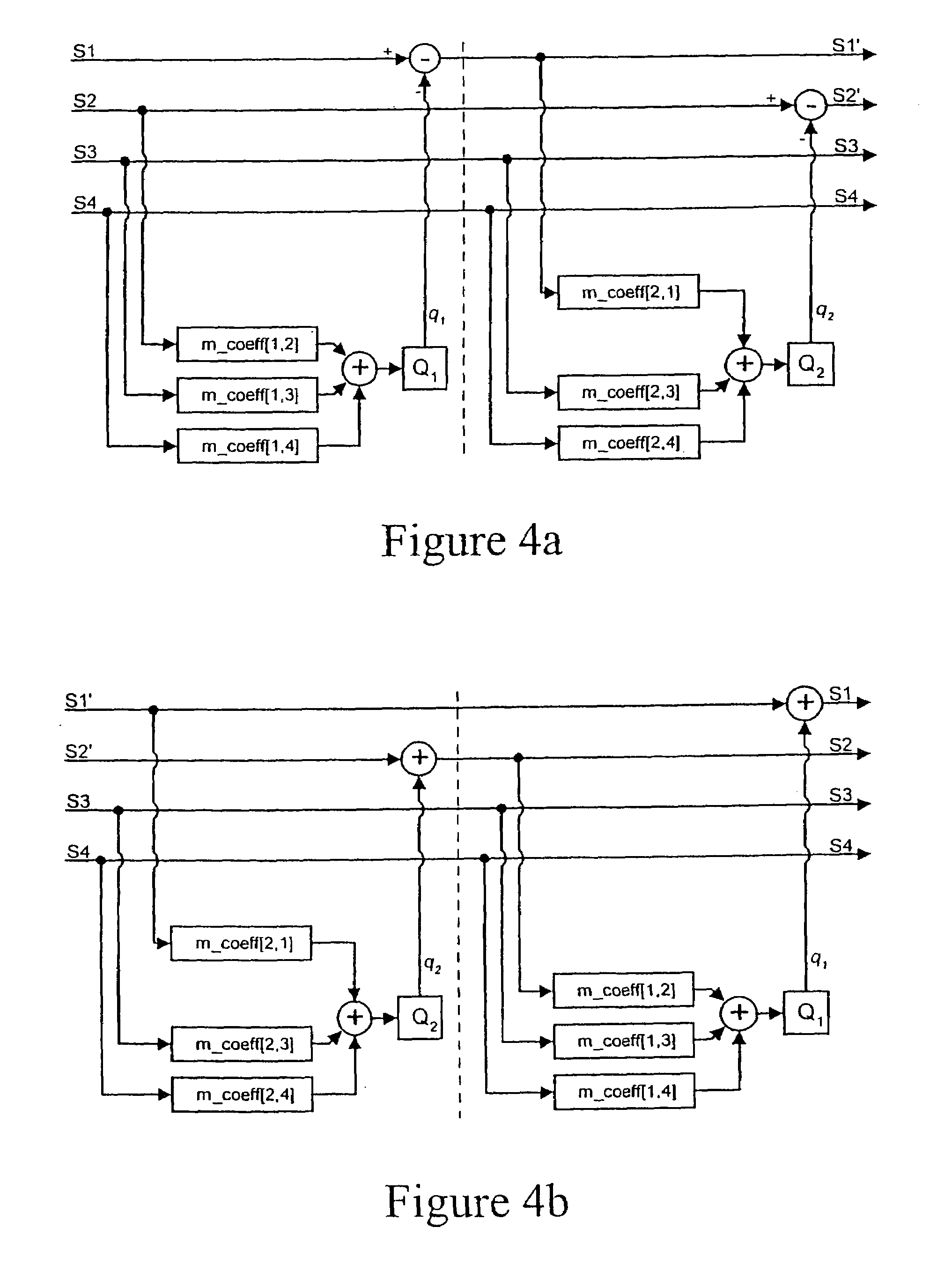
[0011]Preferably, any truncation or rounding within the matrixing should be computed using dither. In this case, for lossless coding, the dither signal must be made available to the decoder in order that it may invert the computations performed by the encoder and thus recover the original signal losslessly. The dither may be computed using an ‘autodither’ method as envisaged in WO-A 96 / 37048; but in the context of a lossless compression scheme, autodither can be avoided by providing a dither seed in the encoded stream that allows a decoder to synchronize its dithering process to that which was used by the encoder.
[0019]Another consequence of the 24-bit tradition in high quality audio is the availability of DSP processing chips having a 24-bit internal word width. Each primitive matrix quantiser as disclosed in WO-A 96 / 37048 modifies one channel of a multichannel signal by adding proportions of the other channels. Such a primitive matrix quantiser has a straight-through gain of unity. The invention in a fourth aspect provides for a primitive matrix quantiser that accepts a gain coefficient for the modified channel, and has an additional data path known as lsb_bypass. The gain may be set to a value less than unity in order to avoid overload. The quantised output of the primitive matrix quantiser will then contain less information than its input, with the remaining information being contained in additional least significant bits (LSBs) that are generated by application of the gain coefficient. Some or all of these LSBs are then transmitted separately through the lsb_bypass data path. In particular, in the case of a gain coefficient of ±½, a single LSB is generated that can be conveyed through the lsb13 bypass.

Problems solved by technology

However this may result in incorrect channel ordering at the output of the decoder's cascade, so preferably a channel permutation is specified by the encoder and implemented by the decoder to recover the correct channel order.

Method used


Image

  • Matrix improvements to lossless encoding and decoding
  • Matrix improvements to lossless encoding and decoding
  • Matrix improvements to lossless encoding and decoding

Examples


Embodiment Construction

Downmix Encoding and Decoding

[0039]The article “Lossless Coding for Audio Discs”, J. Audio Eng. Soc., September 1996, vol. 44, no. 9, pp. 706–720 and international patent application WO-A 96 / 37048 contain discussions of some of the principles used in lossless compression.

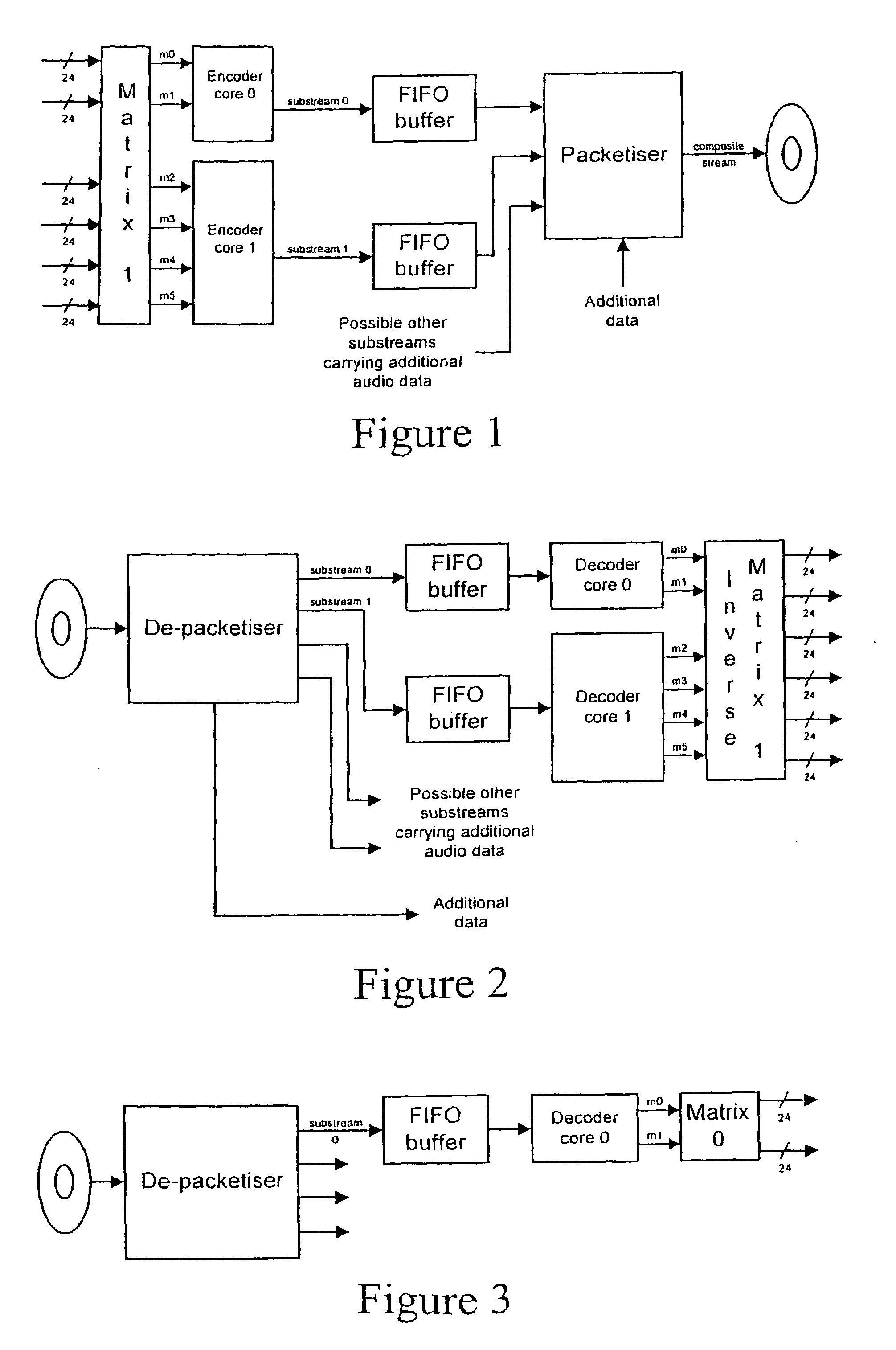
[0040]An important commercial application of lossless compression is on DVD-Audio, where there are two classes of player: the multichannel player furnishing 6 outputs used typically to drive a ‘5.1’ speaker layout, and the two channel player furnishing two outputs for listeners with two loudspeakers or for portable use with headphones.

[0041]Therefore, DVD-Audio has the capability to carry a recorded audio signal twice, once as a multichannel signal and again as a two-channel signal. However, carrying the signal twice has adverse implications for playing time. In many cases the original recording is presented as a multichannel signal only, and the two channel listener is given a downmix derived from the multichannel ...


PUM

PropertyMeasurementUnit
frequenciesaaaaaaaaaa

Abstract

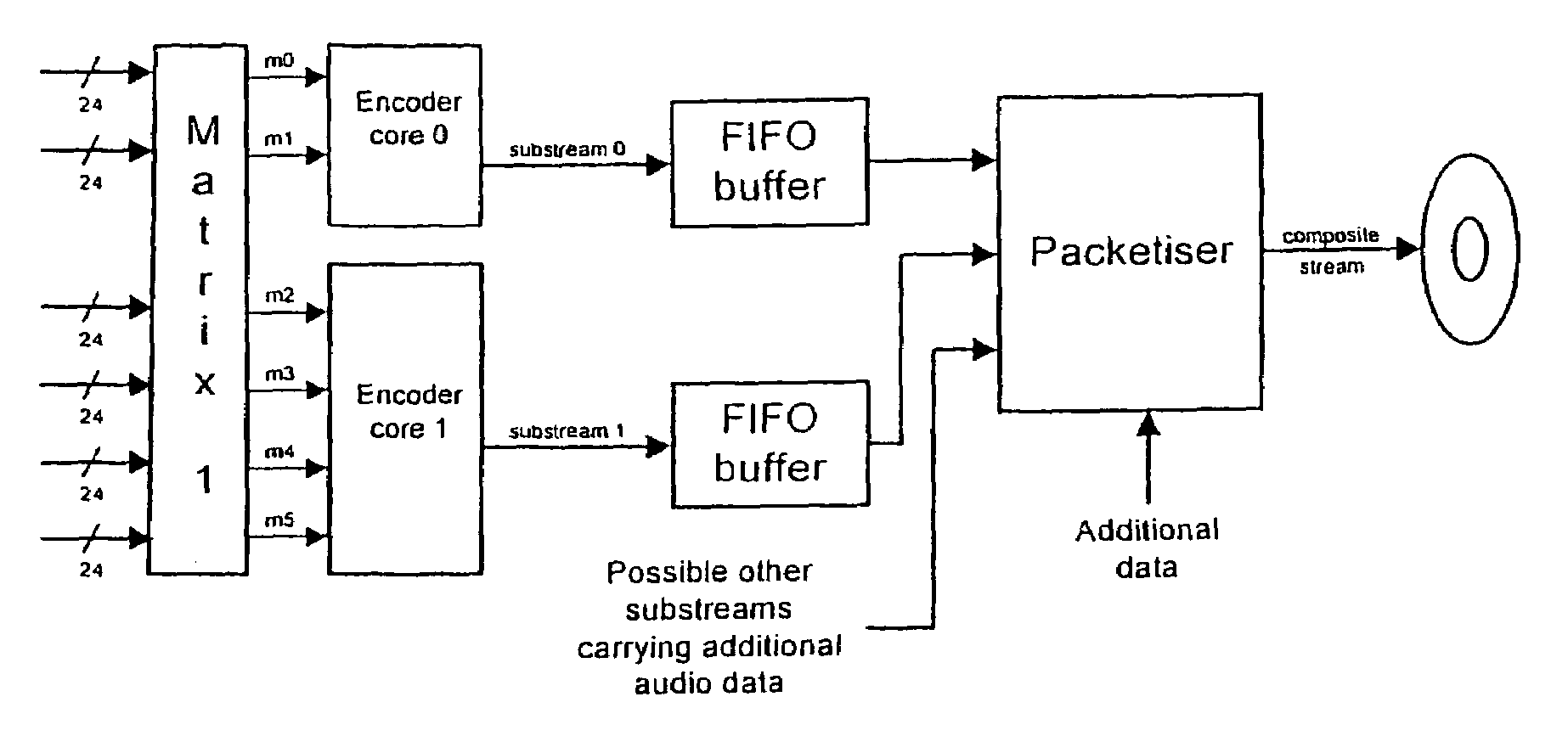
A lossless encoder and decoder are provided for transmitting a multichannel signal on a medium such as DVD-Audio. The encoder accepts additionally a downmix specification and splits the encoded stream into two substreams, such that a two-channel decoder of meagre computational power can implement the downmix specification by decoding one substream, while a multichannel decoder can decode the original multichannel signal losslessly using both substreams. Further features provide for efficient implementation on 24-bit processors, for confirmation of lossless reproduction to the user, and for benign behaviour in the case of downmix specifications that result in overload. The principle is also extended to mixed-rate signals, where for example some input channels are sampled at 48 kHz and some are sampled at 96 kHz.

Description

FIELD OF THE INVENTION[0001]The invention relates to the encoding and decoding of digital signal streams, particularly digital audio streams, with reference to matrixing multichannel signals.BACKGROUND OF THE INVENTION[0002]Lossless compression is now an established means of reducing the data rate required for storing or transmitting a digital audio signal. One method of reducing the data rate of a multichannel signal is to apply matrixing so that dominant information is concentrated in some of the transmitted channels while the other channels carry relatively little information. For example, two-channel audio may have nearly the same waveform in the left and right channels if conveying a central sound image, in which case it is more efficient to encode the sum and difference of the two channels. This process is described in some detail in WO-A 96 / 37048, including the use of a cascade of ‘primitive matrix quantisers’ to achieve the matrixing in a perfectly invertible or lossless man...

Claims


Application Information

Patent Timeline
Patent Type & Authority Patents(United States)
IPC IPC(8): H03M7/00G10L19/00G10L19/008G10L19/02G11B20/00G11B20/10H03M7/30H04H20/88H04N5/76H04S3/02
CPCG11B20/00992G11B20/10527H03M7/30H04H20/88H04N5/76H04S3/02G11B20/00007G11B2020/00014G11B2020/10546H04S2420/03G11B2220/2562H03M7/00
Inventor CRAVEN, PETER GRAHAMLAW, MALCOLM JAMESSTUART, JOHN ROBERT
Owner DOLBY LAB LICENSING CORP
Learn More