Method and system having capacity-dependent baseband gain and coverage-capacity swapping in a multi-carrier base station transmitters

a base station transmitter and multi-carrier technology, applied in multi-frequency code systems, power management, wireless communication, etc., can solve the problems of carrier transmission posing difficult requirements regarding the dynamic range of the transmitter, the inability to reject noise inside the processing bandwidth by analog filtering, and the digital to analog conversion

Active Publication Date: 2007-03-20
NOKIA TECHNOLOGLES OY
View PDF9 Cites 14 Cited by
  • Summary
  • Abstract
  • Description
  • Claims
  • Application Information

AI Technical Summary

Benefits of technology

[0013]The present invention is a transmission system and a method of transmission which transmits an analog composite signal including carriers which are respectively modulated with different digital data signals. A combined digital output signal which is converted from digital to analog representing combining of the digital data signals is controlled in magnitude. The control of the magnitude of the combined digital output signal is made so that as much of the dynamic range of digital to analog conversion of the combined digital signal is used which is practically possible (but not necessarily the maximum) while avoiding clipping of the combined digital output signal by the digital to analog converter. This affords the benefit of allowing the operator of a base station in a wide band multiple carrier environment involving one or more systems, such as GSM or EDGE, to configure a number of channels up to a maximum by permitting a proportionate reduction of the power of the individual channels and also to permit reconfiguration of the transmitter to broadcast fewer carriers at higher power.
[0014]The invention maximizes the available dynamic range of the digital to analog converter and utilizes that range to enhance the base station flexibility and reconfigurability by permitting flexible carrier allocation to suit a number of active mobiles to which the base station is transmitting with the power level of the carriers being adjusted to utilize the dynamic range of the digital to analog converter without clipping the composite digital signal which is formed by combining the individual digital carrier signals. The scaling function (adjustment in magnitude) of the composite digital signal is placed in front of the digital to analog converter in the transmitter chain to adjust the signal level of the composite digital signal. The conversion from digital to analog operates as close as possible to the full scale of the dynamic range irrespective of the actual RF output power. When the invention is utilized in a base station, the number of carriers which are supported may be either a permanent reconfiguration or an on the fly configuration. During a change in the configuration of the number of carriers, the single multiple carrier transmitter including the upstream scaling of the combined digital signal permits the number of channels to be increased up to a maximum with the only penalty being a lower power per carrier resulting in coverage and capacity being control variables at the base station.

Problems solved by technology

However, problems occur from the digital to analog conversion which is necessary for converting the digitally formatted, digitally modulated carrier signals into analog for transmission by a transmitter.
GSM and EDGE standards applied to multiple carrier transmission pose difficult requirements regarding the dynamic range of the transmitter 38.
The difficulty arises because of the processing bandwidth of the transmitter has to be wide enough to host multiple digitally combined carriers produced by the digital domain signal modulators 14 at arbitrary frequency locations within the wide bandwidth of broadcast.
However, the wideband transmitter 38 processing cannot reject noise inside the processing bandwidth by analog filtering.
A large dynamic range requirement of the digital to analog converter 20 determined by the difference between an instantaneous maximum signal power and a noise floor is a critical issue in multiple carrier radio transmitter design.
Furthermore, GSM and EDGE standards do not specifically address multiple radio or even multiple carrier operation.
In the case of a multiple carrier transmitter and an unfavorable interpretation of the GSM or EDGE standards, wideband noise measurement results in rapidly increasing dynamic range demands as the number of carriers is raised.
Since wideband noise is measured with a single full power carrier, a traditional base transceiver station, which combines at the transmitter outputs, experiences an elevated noise floor in normal operation due to noise.
Since multiple radio enables on the fly capacity changes by switching off carriers, constant digital modulator output levels do not use the dynamic range of the digital to analog converter efficiently.
If the carrier input levels to the digital to analog converter are fixed based on the maximum number of simultaneous carriers, some digital to analog converter dynamic range is wasted when the number of carriers is smaller than the maximum.
This occurs as a result of the composite peak power of a smaller number of carriers never achieving levels needed to reproduce a maximum number of carriers in an undistorted manner.

Method used


Image

  • Method and system having capacity-dependent baseband gain and coverage-capacity swapping in a multi-carrier base station transmitters
  • Method and system having capacity-dependent baseband gain and coverage-capacity swapping in a multi-carrier base station transmitters
  • Method and system having capacity-dependent baseband gain and coverage-capacity swapping in a multi-carrier base station transmitters

Examples


Embodiment Construction

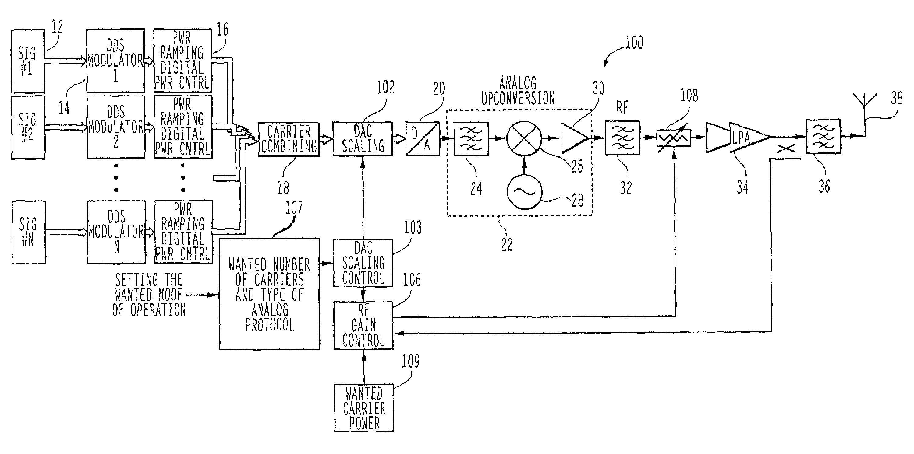
[0027]FIG. 4 illustrates a block diagram of an embodiment 100 of the present invention. A digital to analog converter scaling function 102, is placed in front of the digital to analog converter 20 in the transmitter chain to adjust the signal level of the composite digital signal produced by the signal combiner. The scaling function 102 may without limitation be a multiplier, as illustrated in FIG. 5, a five-bit multiplier as illustrated in FIG. 6, a multiplier with a multiplexer bypass in FIG. 7 which permits the multiplication function of FIG. 5 to be selectively disabled so that the input signal to the digital to analog converter 20 is unchanged or a bit shifter 300 as illustrated in FIG. 8. The digital scaler 102 receives as an input the combined digital carrier signals produced by the signal combiner 18. The digital to analog converter 20 has a dynamic range which converts a specified maximum number of bits, such as 12 bits, into the corresponding analog output signal. As descr...


PUM


Abstract

The invention is a method and transmission system which transmits an analog composite signal, including carriers which are respectively modulated with different digital data signal. A transmission system in accordance with the invention includes a signal combiner (18), responsive to the digital data signals, which are provided as inputs to the signal combiner, the signal combiner providing an output of a combined digital signal representing combining of the digital data signals; a multiple carrier transmitter (38) which transmits the analog composite signal; a digital to analog converter (20) which converts a composite digital signal input into the analog composite signal, the digital to analog converter having a dynamic range of digital to analog conversion; and a digital scaler (102), responsive to the combined digital signal provided by the signal combiner, which outputs the composite digital signal that is digital to analog converted by the digital to analog converter, the composite digital signal being a function of the combined digital signal provided by the signal combiner and having a controlled magnitude which results in as much of the dynamic range of the digital to analog converter as possible being used during digital to analog conversion of the composite digital signal without clipping the composite digital signal.

Description

BACKGROUND OF THE INVENTION[0001]The present invention relates to multiple carrier transmitters and more particularly, to substantially full utilization of the dynamic range of a digital to analog converter used in a transmitter which converts a combined digital carrier signal into a analog signal without clipping the combined digital carrier signal.DESCRIPTION OF THE PRIOR ART[0002]A multiple radio covering multiple standards in multiple bands using multiple carriers is a highly sought after transmitter architecture in a cellular base station. Multiple radios promise significant cost savings through component module and platform use and potentially quicker product development because a variety of products can be based on a single radio platform. A multiple radio platform used in a base station can provide an operator with a range of configuration options. Moreover, switching between standards and having the function of transmitting signals with different characteristics, such as en...

Claims


Application Information

Patent Timeline
Patent Type & Authority Patents(United States)
IPC IPC(8): H04L25/00H04B7/005H04L27/28
CPCH04L27/28H04W52/346H04W52/343H04W52/42
Inventor HONKANEN, MAURIDEKKER, ANDREWASKO, STEPHEN
Owner NOKIA TECHNOLOGLES OY
Why Eureka
Try Eureka