Subcutaneous cardiac stimulator with small contact surface electrodes

a technology of contact surface electrodes and subcutaneous electrodes, which is applied in the direction of subcutaneous electrodes, internal electrodes, therapy, etc., can solve the problems of abnormal performance of av nodes, improper conduct of rest, and heart's own natural pacemaker, so as to reduce the resistance of electrode interfaces

Inactive Publication Date: 2007-03-20
CAMERON HEALTH
View PDF124 Cites 162 Cited by
  • Summary
  • Abstract
  • Description
  • Claims
  • Application Information

AI Technical Summary

Benefits of technology

[0030]In one embodiment, the outer surface of either or both electrodes is also a conductive surface so that when the respective electrode is implanted, the outer surface is in electrical contact with the body tissues as well, thereby reducing the electrode interface resistance. In an alternate embodiment, the outer surface of one or both electrodes can be coated with a non-conductive material.

Problems solved by technology

Bradycardia often results from abnormal performance of the AV node.
Stimuli generated by the heart's own natural pacemaker, the SA node, are improperly conducted to the rest of the heart's conduction system; as a result, other stimuli are generated although their intrinsic rate is below the SA node's intrinsic rate.
Tachycardia often results from ischemic heart disease in which local myocardium performance is compromised As a result of tachycardia, coordinated contraction of heart tissue is lost which leads to a loss of blood flow to the rest of the body.
This system is very complicated and it is difficult to implant surgically since it requires three separate incisions.
However, commercially available ICDs have several disadvantages.
First, they must be implanted using somewhat complex and expensive surgical procedures that are performed by specially trained physicians.
Second, they rely on transvenous leads for the placement of at least one electrode within the cardiac chambers.
It has been found that over a period of time the electrodes get dislodged from the cardiac tissues, undesirable tissue formations may deposit on the electrodes, or the leads can break.
These problems are especially acute when leads carry two or more electrodes.
Third, removing these ICDs and replacing them, if necessary, also requires complicated surgical procedures that may be more life-threatening than the initial implantation.
Moreover, because the electrodes are applied externally, an AED typically requires more power than an ICD.
All three types of AEDs require the application of external electrodes which are uncomfortable.

Method used


Image

  • Subcutaneous cardiac stimulator with small contact surface electrodes
  • Subcutaneous cardiac stimulator with small contact surface electrodes
  • Subcutaneous cardiac stimulator with small contact surface electrodes

Examples


Embodiment Construction

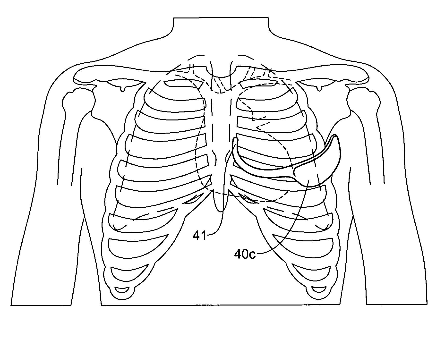
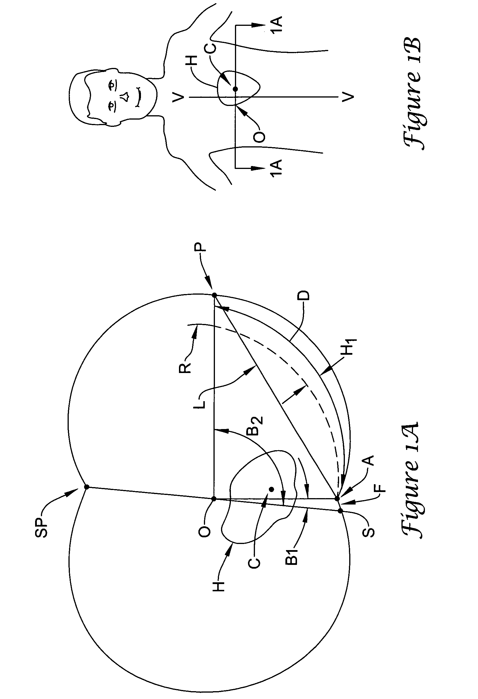
[0052]The present invention pertains to a novel device and method for applying stimulation to the heart of a patient. Before the device is described, several terms are first defined. FIG. 1A shows a cross sectional view and FIG. 1B is an elevational view of a standing patient. The heart of the patient is indicated at H as having a center of mass C. FIG. 1A also shows the sternum S and the spine SP. An imaginary line joins points S and SP, having a midpoint O. The vertical axis V—V through point O is defined as the central axis of the patient.

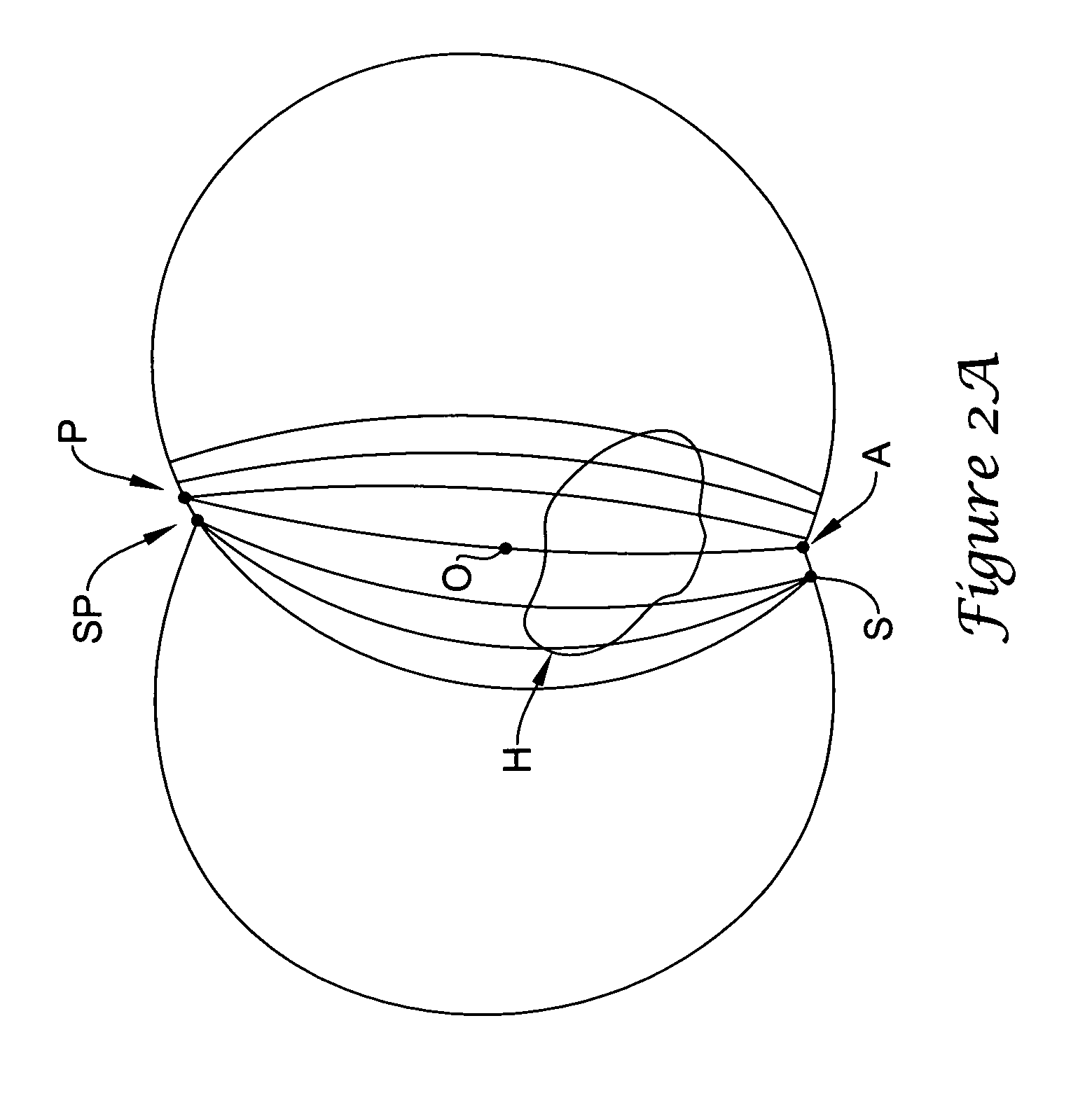
[0053]The present application is concerned with the optimal locations of two subcutaneous electrodes A (for anterior) and P (for posterior). These electrodes are implanted between the skin and the rib cage. As seen in FIG. 1A, electrode A is located as close to the sternum as possible. Its position is defined by the angle B1 between lines OS and OA. Similarly, the position of electrode P is defined by the angle B2 between the lines OS and OP. As...


PUM


Abstract

A subcutaneous cardiac device includes two electrodes and a stimulator that generates a pulse to the electrodes. The electrodes are implanted between the skin and the rib cage of the patient and are adapted to generate an electric field corresponding to the pulse, the electric field having a substantially uniform voltage gradient as it passes through the heart. The shapes, sizes, positions and structures of the electrodes are selected to optimize the voltage gradient of the electric field, and to minimize the energy dissipated by the electric field outside the heart. More specifically, the electrodes have contact surfaces that contact the patient tissues, said contact surfaces having a total contact area of less than 100 cm2. In one embodiment, one or both electrodes are physically separated from the stimulator. In another embodiment a unitary housing holds the both electrodes and the stimulator. Sensor circuitry may also includes in the stimulator for detecting intrinsic cardiac activity through the same electrodes.

Description

RELATED APPLICATIONS[0001]This application is a continuation-in-part application to the following applications, all of which are incorporated herein by reference: U.S. application Ser. No. 09 / 663,607, filed Sep. 19, 2000 and entitled “Subcutaneous Only Implantable Cardioverter-Defibrillator and Optional Pacer”, now U.S. Pat. No. 6,721,597; U.S. application Ser. No. 09 / 663,606, filed Sep. 19, 2000 and entitled “Unitary Subcutaneous Only Implantable Cardioverter-Defibrillator And Optional Pacer”, now U.S. Pat. No. 6,647,292; U.S. application Ser. No. 09 / 940,283, filed Aug. 27, 2001 and entitled “Duckbill-Shaped Implantable Cardioverter-Defibrillator Canister and Method of Use”, now U.S. Pat. No. 7,065,407; U.S. application Ser. No. 09 / 940,371, filed Aug. 27, 2001 entitled “Ceramics and / or Other Material Insulated Shell for Active and Non-Active S-ICD Can”, now U.S. Pat. No. 7,039,463; U.S. application Ser. No. 09 / 940,468, filed Aug. 27, 2001 and entitled “Subcutaneous Electrode for Tr...

Claims


Application Information

Patent Timeline
Patent Type & Authority Patents(United States)
IPC IPC(8): A61N1/39A61N1/362A61N1/375
CPCA61N1/3931A61N1/3912A61N1/3756A61N1/3968A61N1/0504
Inventor BARDY, GUST H.CAPPATO, RICCARDOOSTROFF, ALAN H.RISSMANN, WILLIAM J.SANDERS, GARY H.
Owner CAMERON HEALTH
Why Eureka
Try Eureka