Apparatus and method for testing stiffness of articles

a technology of stiffness and apparatus, applied in the field of apparatus and methods for the testing of stiffness, can solve the problems of limited use of such apparatus, inability to implement real-time dynamic testing procedures for all pieces, and inability to test the stiffness of objects in real-time, and achieve the effect of reliable stiffness estimation

Active Publication Date: 2007-03-27
CENT DE RES & DEV IND DU QUEBEC
View PDF15 Cites 12 Cited by
  • Summary
  • Abstract
  • Description
  • Claims
  • Application Information

AI Technical Summary

Benefits of technology

[0009]It is therefore a main object of the present invention to provide apparatus and method for testing stiffness of an article that allow compact implementation while providing reliable stiffness estimation.

Problems solved by technology

Although such static approach has become considered in the wood processing industry as a standard procedure whose results are widely employed as reference values according to which MSR grades are established, in the context of on-line quality procedures, its use is limited to the testing of sampled pieces coming from the production line, and cannot be implemented as a real-time, dynamic testing procedure for all pieces being processed while they are conveyed through the production line.
While representing an improvement over the static testing approach as to the capability of these prior dynamic testing apparatus to systematically test all pieces of lumber as they are processed in the production line, the use of such apparatus is limited to industrial installations where there is sufficient available space within the production line to receive these prior art apparatus whose dimensions generally exceed the length of the longer piece of lumber to be processed.
The use of roll-based load applying device as taught by the above-mentioned prior patents is associated with problems related to load measurement signals stability which adversely affects consistency and reliability of stiffness estimation.
The fact that a load applying roll is characterized by a loading surface that is limited to a peripheral portion of its circumference adjacent the loaded surface of the article in the conveying direction yields to such load measurement signal stability problems, especially in cases where significant vibration occurs when the article is transported on the conveyer.
The ultimate effect of this limitation is to yield inconsistent stiffness estimation that may result to classification errors such as under-grading or over-grading of pieces of lumber.
Such prior art apparatus carrying out a single load measurement corresponding to a single deflection measurement to obtain the desired bending stress limit measurement, the significant influence of bow and warp that are naturally present on most pieces of lumber cannot be adequately compensated according to the proposed technique.

Method used


Image

  • Apparatus and method for testing stiffness of articles
  • Apparatus and method for testing stiffness of articles
  • Apparatus and method for testing stiffness of articles

Examples


second embodiment

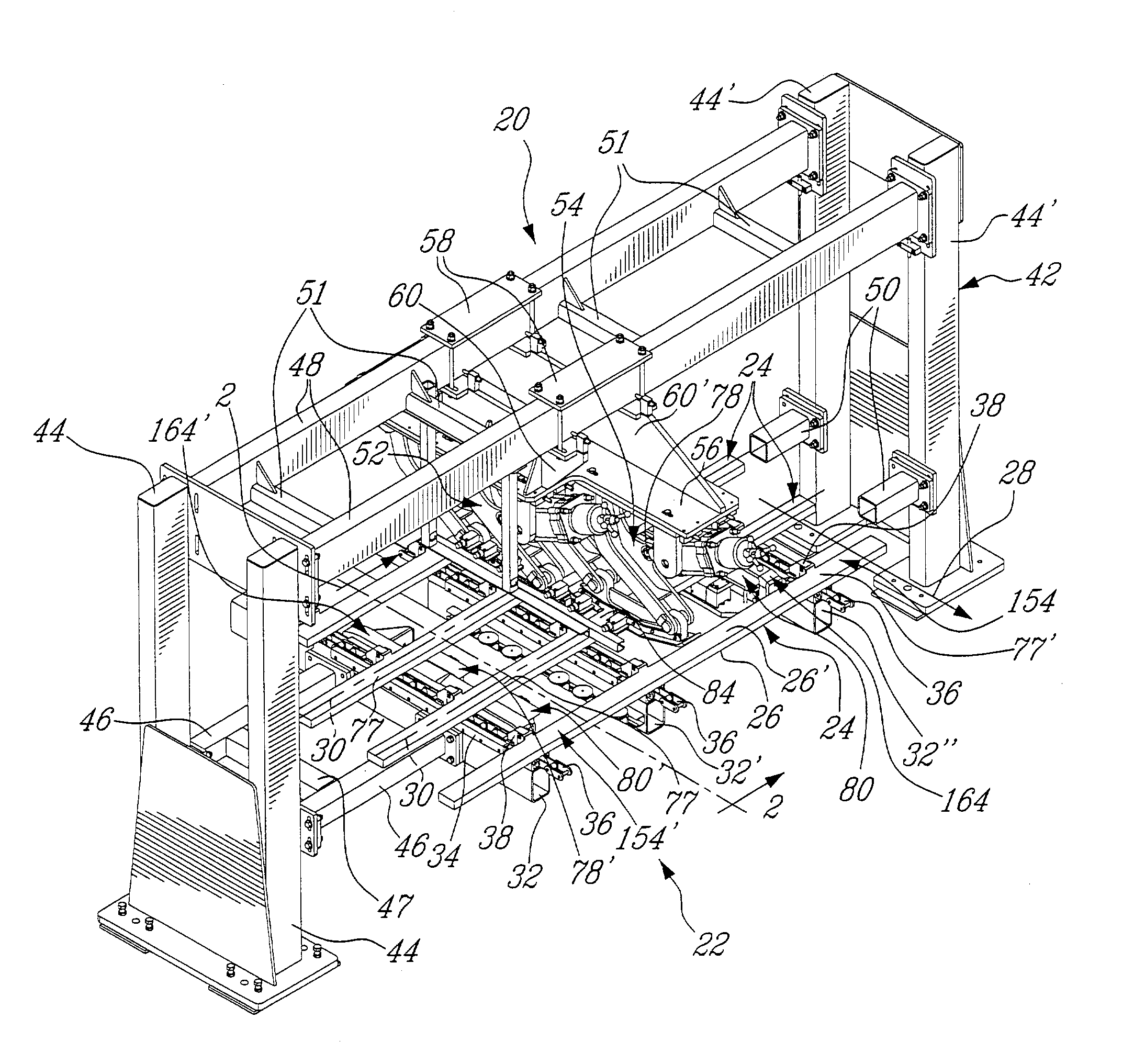
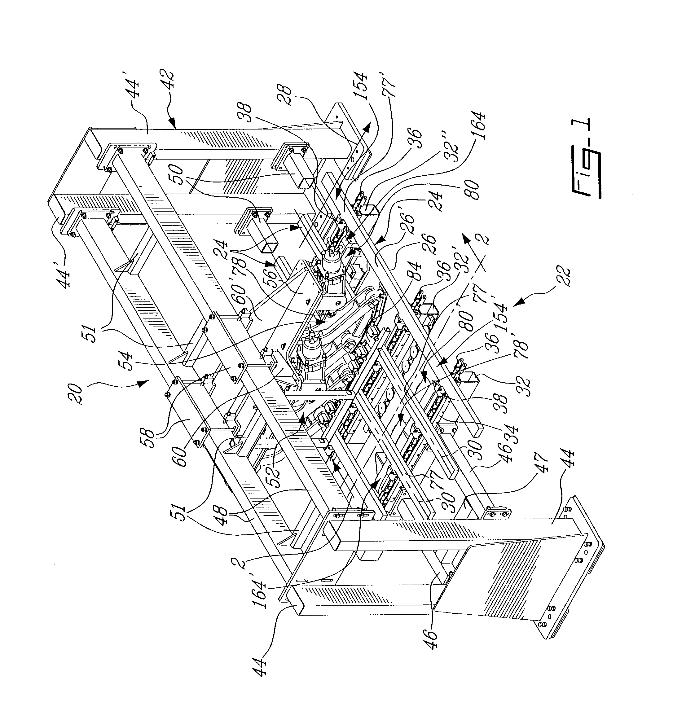
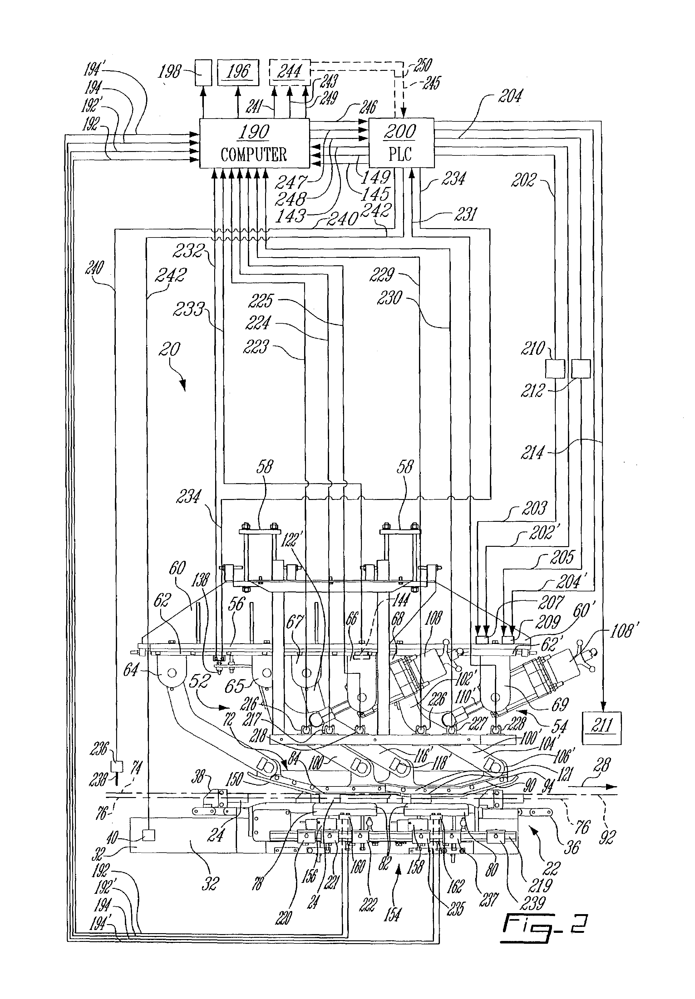
[0094]Turning back to FIG. 15, the apparatus 20′ further includes first and second load measuring units generally designated at 179, 181 and respectively associated with first and second deflecting units 52, 54′. The first load measuring unit 179 is formed by a pair of right and left sides subunits 183, 183′ mechanically coupled to first and second rails 78, 78′ of the first bearing unit as shown in FIG. 14, and the second measuring unit 181 is formed by a similar pair of right and left sides subunits 185, 185′ mechanically coupled to the pushing devices 264, 264′ provided on the second bearing unit as will be described later in more detail. Load measuring units 179, 181 are capable of generating signals indicative of respective magnitudes of first and second thrusts as applied by first and second deflecting units 52, 54′ as will be later explained in more detail.

[0095]Turning now to FIG. 19, first (right) rail 78 as part of the first article bearing unit is shown with a correspond...

first embodiment

[0111]On the basis of the above calculations, according to a similar approach used for the first embodiment, the computer preferably applies a correction to the nominal deflection values as set prior to the operation of the apparatus, to compensate the inherent deformation to which the whole structural components of the apparatus are subjected, such as flexion of load cells 156,158, overhead beams 48, first deflecting unit 52 and pushing devices 264, 264′ associated with second deflecting unit 54′.

[0112]The correction is made on the basis of estimated deflection error values associated with first and second deflection values d1, d2 as calculated as follows:

[0113]ErD1=(NetLoad12*KCell1)+(NetLoad22*KCell2)+(InD1⁢TwistD12)(20)ErD2=(InD2⁢LeftPush+InD2⁢RightPush2)-(TwistD22)⁢(21)

with:

InD1=KS1,1*(NetLoad1+NetLoad2)+KS2Left,1*NetLoad3+KS2Right,1*NetLoad4+K1,1*(NetLoad1+NetLoad2)  (22)

InD2LeftPush=KS1,2Left*(NetLoad1+NetLoad2)+KS2Left,2Left*NetLoad3+KS2Right,2Left*NetLoad4+K2,2*NetLoad3  (2...


PUM

PropertyMeasurementUnit
conveying speedaaaaaaaaaa
symmetrical angleaaaaaaaaaa

Abstract

An apparatus for testing stiffness characteristics such as modulus of elasticity E of an article such as a piece of lumber moving in a conveying direction transverse to the testing axis, comprises a bearing unit capable of contacting the piece of lumber at two spaced apart portions thereof. There is provided a first deflecting unit including a first working element being normally disposed in a first static position relative to the conveying path for applying a first thrust against a loaded area on the article at an intermediary portion thereof located between the spaced apart portions, to produce an article deflection of a first magnitude. Each working element defines a loading surface extending substantially parallel to the article-conveying path. There is further provided a second deflecting unit including a second working element being normally disposed in a second static position relative to the conveying path for applying a second thrust against a loaded area of the article intermediary portion, to produce an article deflection of a second magnitude, wherein the second position differs from the first position relative to the conveying path by a differential value. The apparatus further comprises load cells coupled to the bearing unit for generating signals indicative of respective magnitudes the first and second thrusts as applied by first and second deflecting units, and a computer for deriving from such signals and differential value an indication of the stiffness of the article, such as modulus of elasticity E.

Description

FIELD OF THE INVENTION[0001]The present invention relates generally to the field of structural products testing, and more particularly to apparatus and methods for the testing of stiffness of such products, and is particularly useful for carrying out Machine Stress Rating (MSR) tests for the purpose of grading lumber according to stiffness characteristics.BRIEF DESCRIPTION OF THE BACKGROUND ART[0002]Over the past years, stiffness testing of structural products has been widely used in manufacturing and building industries as an important quality concern warranting security of use of these products in the field. Stiffness characteristics of structural products are usually tested through the measurement of a parameter known as modulus of elasticity (E) also known as Young modulus, which is essentially defined as the ratio of the magnitude of a load applied to the article over the magnitude of the corresponding deformation induced to the same article as a result of the applied load. In ...

Claims


Application Information

Patent Timeline
Patent Type & Authority Patents(United States)
IPC IPC(8): G01N3/20G01N3/00G01N3/02G01N33/46
CPCG01N3/20G01N33/46G01N2203/0023G01N2203/0258G01N2203/0206G01N2203/0248G01N2203/0075
Inventor OUELLET, JEAN-CLAUDECAMPAGNA, JEANDUPONT, DANICKBEAUCHEMIN, GRATIENLABBE, JACQUES
Owner CENT DE RES & DEV IND DU QUEBEC
Why Eureka
Try Eureka