Eureka AIR delivers breakthrough ideas for toughest innovation challenges, trusted by R&D personnel around the world.

System and a method for cooling a tool

Inactive Publication Date: 2007-03-27
EDMOND DANTES HLDG LLC
View PDF73 Cites 15 Cited by
  • Summary
  • Abstract
  • Description
  • Claims
  • Application Information

AI Technical Summary

Benefits of technology

[0008]It is a first non-limiting advantage of the present invention to provide a method for creating cooling passages within a tool which overcomes some or all of the previously delineated drawbacks of prior techniques.
[0009]It is a second non-limiting advantage of the present invention to provide a method for creating a tool which overcomes some or all of the previously delineated drawbacks and which, by way of example and without limitation, allows for the efficient formation of cooling passages within the tool.
[0010]It is a third non-limiting advantage of the present invention to provide a tool having cooling passages which may be efficiently and integrally formed within the tool and which allow a created item to be efficiently cooled while concomitantly increasing the quality of the produced part.
[0011]According to a fourth advantage of the present invention, a tool is provided. Particularly, the tool comprises a plurality of sectional members which are coupled together, wherein the plurality of sectional members each have at least one coolant passage and at least one of the plurality of section members has an outer contour which is disposed a certain minimum distance from the at least one coolant passage.
[0012]According to a fifth advantage of the present invention a laminated tool having improved cooling characteristics is provided. Particularly, the laminated tool comprises a plurality of first sectional members each having a certain contour and at least one cooling passage which is a certain predetermined distance from the forming surface; wherein the plurality of sectional members are coupled together, effective to cause the certain contours to form a forming surface and to cause the at least one cooling passages to form a cooling manifold; and an amount of material which is disposed within the cooling manifold, effective to cool the tool.
[0013]According to a sixth advantage of the present invention, a method is provided for forming a tool having improved cooling characteristics. The method comprises the steps of forming at least one first member having a first outer contour and at least one first inner passage which is disposed a certain predetermined distance from the first outer contour; forming at least one second member having a second outer contour and at least one second inner passage which is disposed the certain predetermined distance from the second outer contour; and attaching the at least one first member to the at least one second member wherein the first outer contour cooperates with the second outer contour to form a mold surface and the first inner passage is communicatively coupled to the second inner passage to form a manifold.

Problems solved by technology

The created heat may cause the produced product to be “deformed” or to be an undesired shape or configuration.
While the foregoing approach does allow for the creation of cooling passages, it represents a relatively inefficient and costly process which undesirably increases the overall cost of production and may undesirably create distortion in the formed part.
Such distortion is particularly undesirable since many of these parts are relatively expensive and may not be salvagable.
Thus, the distorted parts must be scrapped which adds cost and inefficiency to the manufacturing process.
Therefore, cooling holes which are drilled into a tool must be at least a minimum distance from the lowest or deepest contour cut into the mold and portions of the mold which are not cut as deep as the lowest contour have more material (i.e., metal) to conduct heat through and undesirably cause uneven / inefficient cooling of the tool.

Method used


Image

  • System and a method for cooling a tool
  • System and a method for cooling a tool
  • System and a method for cooling a tool

Examples


Embodiment Construction

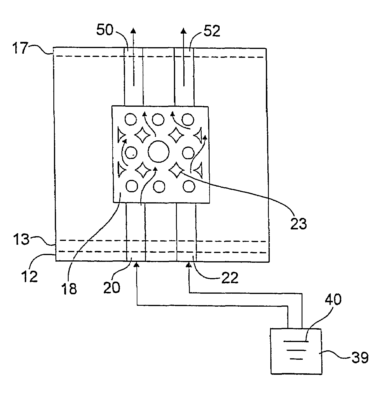
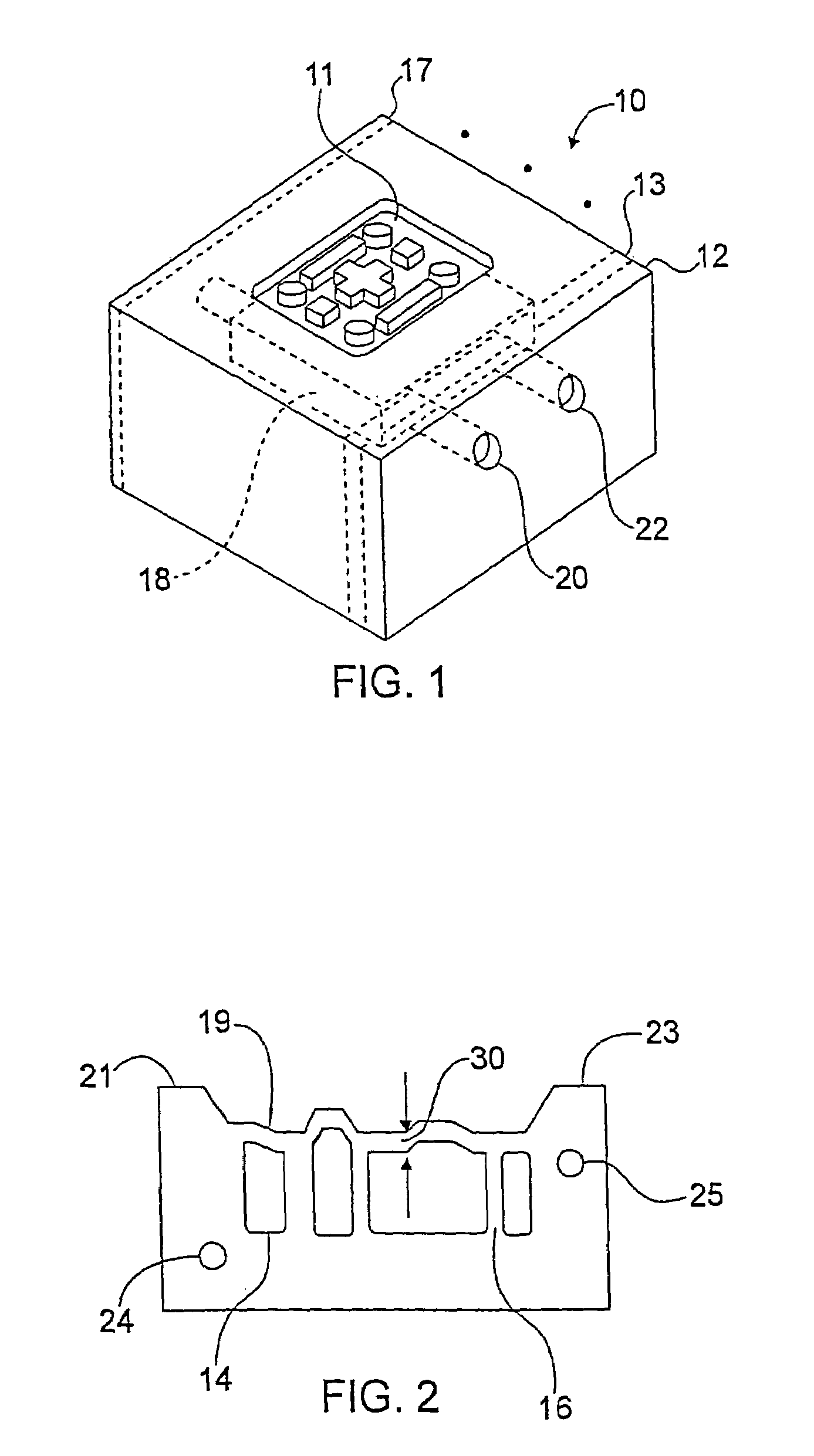
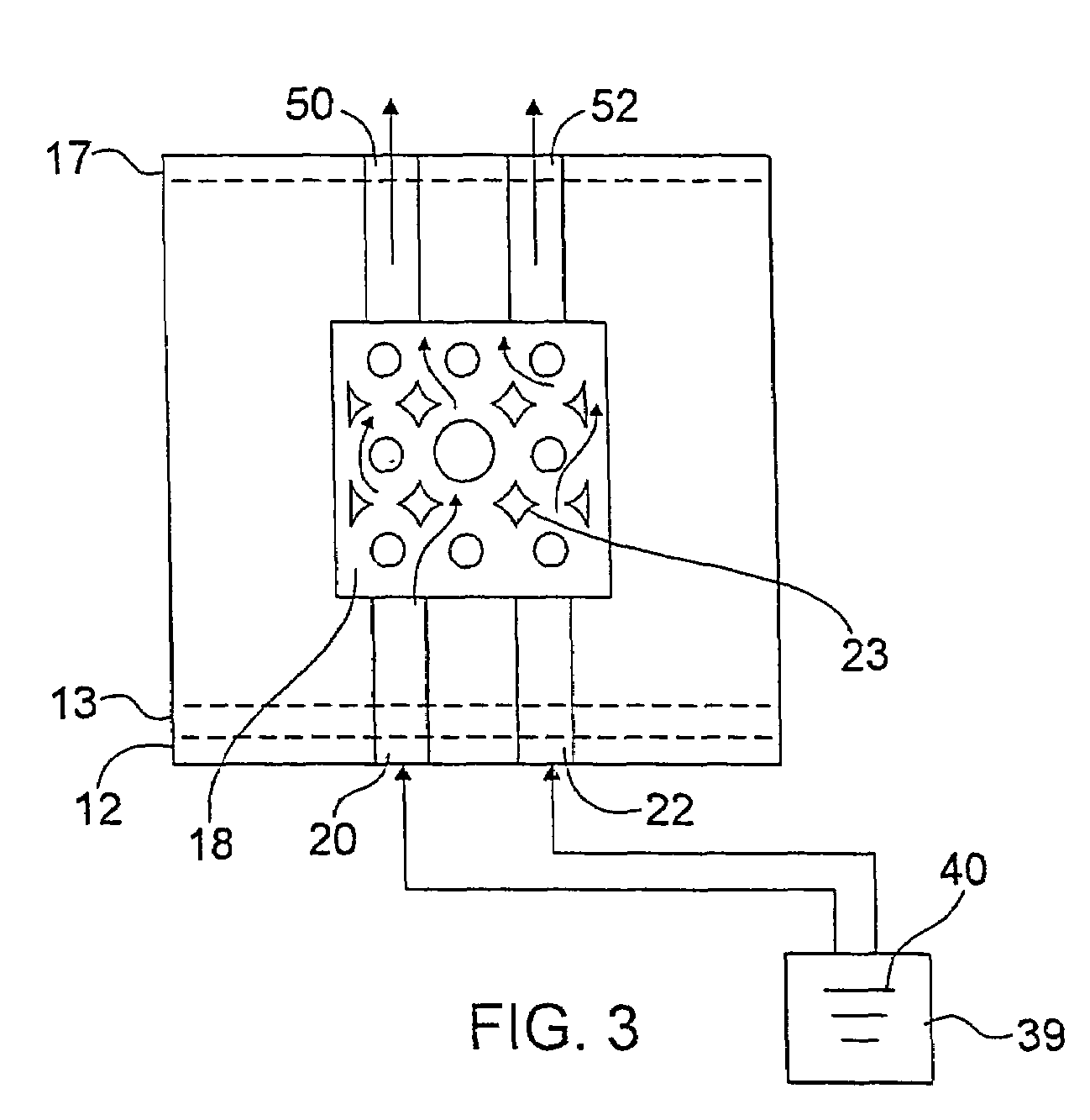
[0019]Referring now to FIGS. 1 and 2, there is shown a tool 10 which is made in accordance with the teachings of the preferred embodiment of the invention. It should be realized that tool 10 may be of any substantially desired shape or geometric configuration and that nothing in this Application is intended to limit the applicability of the invention to a particular type of tool or apparatus. Rather, the tool 10 is only one non-limiting example of a tool which may be produced according to the invention. In the preferred embodiment of the invention, tool 10 comprises a mold member having a contoured forming or mold surface 11.

[0020]As shown best in FIGS. 1 and 2, mold surface 11 is formed by the coupling of a plurality of adjacent sectional members (e.g., members 12–17). That is, at least one of these sectional members 16 include a predetermined contour or shape 19 formed into its “top” surface 21. As each adjacent section member 12–17 is connected together, each contour 19 cooperate...


PUM

PropertyMeasurementUnit
Timeaaaaaaaaaa
Timeaaaaaaaaaa
Thicknessaaaaaaaaaa

Abstract

A tool (10) having improved heat transfer characteristics and a method for cooling a tool (10) which is comprised of several selectively coupled sectional members (12–17) Each selected sectional members (16) include an outer contour (19), while each of the sectional members (12–17) includes at least one coolant passage (14). These coolant passages (14) cooperatively form a coolant manifold (18) which is a predetermined distance from contours (19). An amount of coolant 40 is passed through manifold (18) to cool tool (10).

Description

FIELD OF THE INVENTION[0001]The present invention generally relates to a tool and to a method for cooling a tool and more particularly, to a laminated tool which is formed by the creation and the selective coupling of members which have a plurality of passages and which are rigidly and selectively sealed in an efficient manner, thereby allowing for the creation of a relatively strong tool having an internal coolant manifold in an efficient and relatively inexpensive manner.BACKGROUND OF THE INVENTION[0002]A tool, such as a mold, die, or other object formation apparatus is used to repeatedly form or create substantially similar objects or products. Conventionally, the tool is formed by machining or “working” a block of material in a certain manner, thereby forming or creating the tool in a desired shape and geometrical configuration. Alternatively, the tool may be formed by a laminar process in which various sectional members are created and selectively coupled, effective to allow th...

Claims


Application Information

Patent Timeline
IPC IPC(8): B29C33/04B21D37/16B21J1/06B29C45/73
CPCB21D37/16B21J1/06B29C33/04B29C45/7312Y10T29/49826B29C2045/7362B29C2045/7393Y10S425/03B29C2045/7318
Inventor MANUEL, MARKGREAVES, THOMAS N.
Owner EDMOND DANTES HLDG LLC
Why Eureka
Eureka Blog
Learn More