Method and apparatus for charging batteries in a system of batteries

a battery and battery system technology, applied in the field of battery chargers, can solve the problems of limiting the ability of batteries or battery banks to be efficiently charged, placing an increasing load on the charger, and difficult to adapt to diode-isolated systems

a battery and battery system technology, applied in the field of battery chargers, can solve the problems of limiting the ability of batteries or battery banks to be efficiently charged, placing an increasing load on the charger, and difficult to adapt to diode-isolated systems

US7196494B2Active Publication Date: 2007-03-27XANTREX LLC

Image

  • Method and apparatus for charging batteries in a system of batteries
  • Method and apparatus for charging batteries in a system of batteries
  • Method and apparatus for charging batteries in a system of batteries

Examples


first embodiment

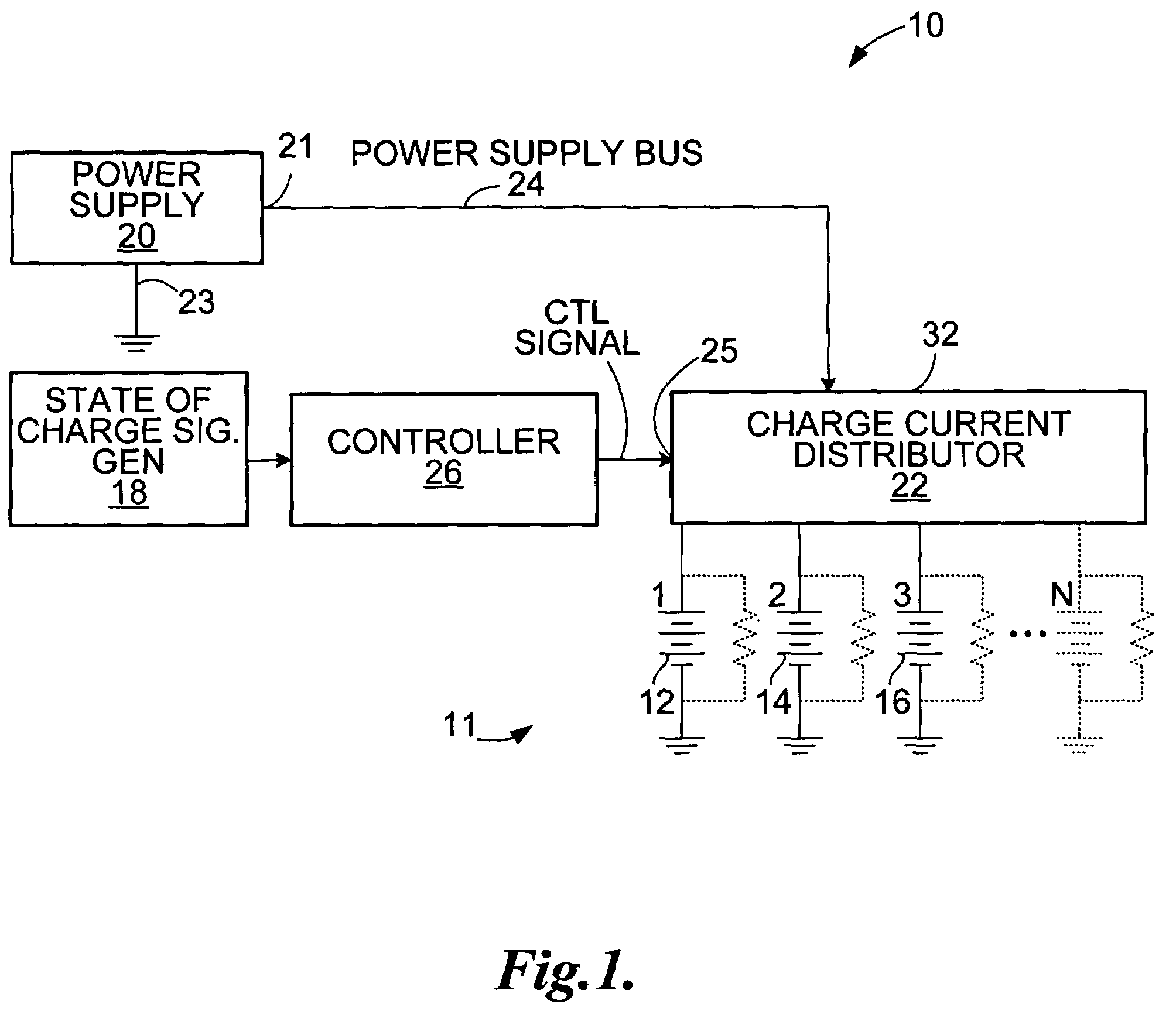
[0032]An apparatus for charging the batteries 12, 14, and 16 in the system, according to the invention is shown generally at 10. Generally, the apparatus 10 includes a state of charge signal generator 18 operable to produce state of charge signals indicative of the states of charge of each battery 12, 14, and 16 in the system 11. The apparatus 10 further includes a power supply 20 operable to produce a charging current and further includes a current distributor 22. Desirably the power supply may be controllable in that its voltage and current may be controlled. The power supply may be of the constant voltage, or constant current types.

[0033]The power supply 20 has positive and negative poles 21 and 23. The positive pole 21 is connected to the current distributor 22 by a power supply bus 24 and the current distributor is operable to selectively connect each battery 12, 14 and 16 in the battery system 11 to the power supply bus 24, in response to a control signal. The apparatus 10 fur...

second embodiment

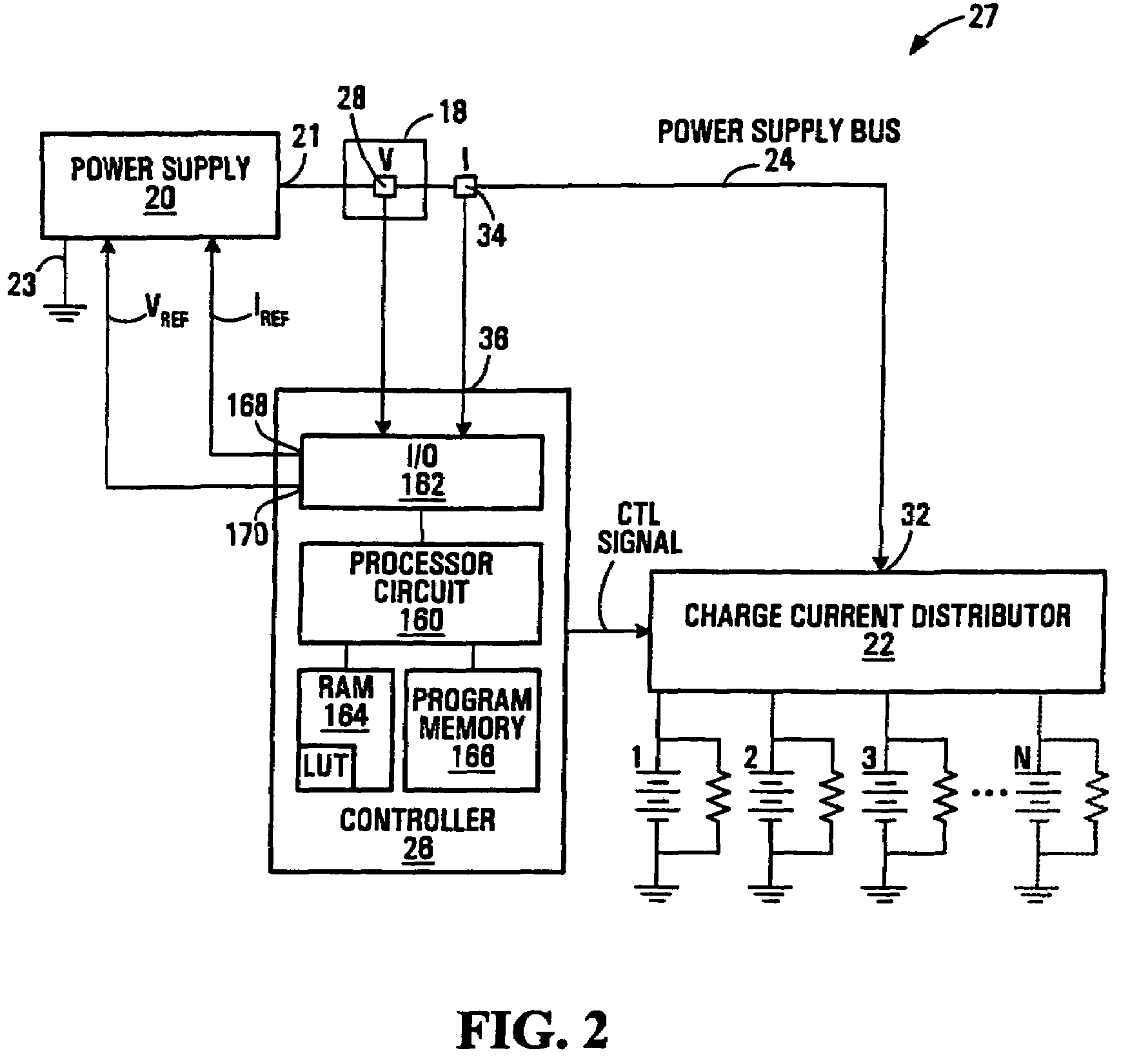
[0034]The state of charge signal generator 18 may include any device that produces a signal indicative of the state of charge of a battery 12, 14 and 16 in the battery system 11. Referring to FIG. 2, the invention is shown at 27 in which the state of charge signal generator 18 includes a voltage sensor 28 in communication with the power supply bus 24 to measure voltage on the power supply bus 24 when the current distributor 22 connects the power supply bus 24 to the most discharged battery. Alternatively separate voltage sensors (not shown) may be used on each charging port.

[0035]The apparatus 10 may include a current signal sensor 34 operable to sense current on the power supply bus 24 and operable to produce a current signal for reception at an input 36 of the controller 26.

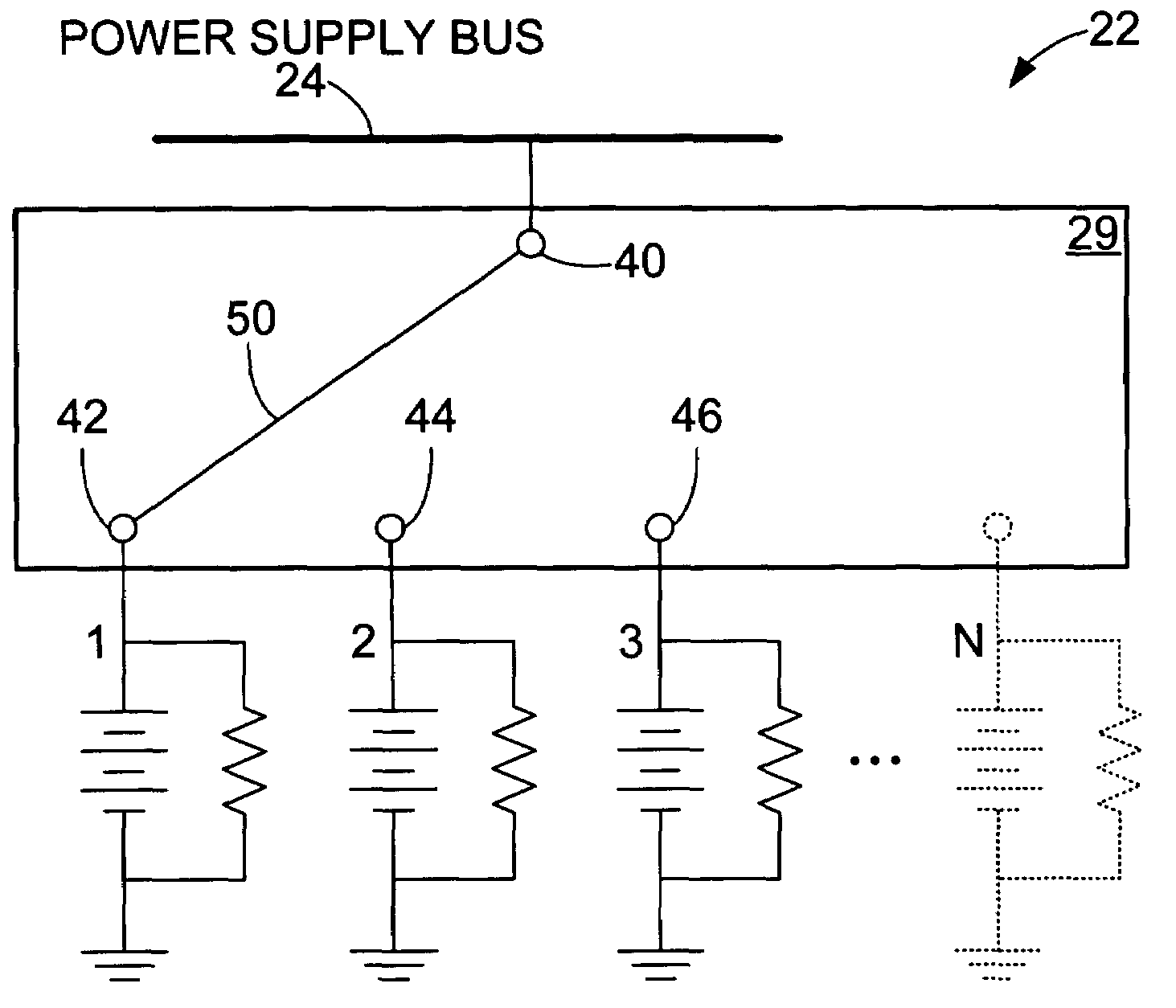
[0036]Referring to FIG. 3, the charge current distributor 22 may include a switching circuit 23 implemented as a single pole multi-throw switch having a common contact 40 connected to the power supply bus 24 an...


PUM

PropertyMeasurementUnit
timeaaaaaaaaaa
timeaaaaaaaaaa
timeaaaaaaaaaa

Abstract

A method and apparatus for charging batteries in a system of batteries. The method and apparatus involve producing a set of state of charge signals indicative of the states of charge of each battery in the system, successively identifying, from the state of charge signals, a most discharged battery in the system and applying a charging current to the most discharged battery for at least part of a first period of time less than a period of time required to fully charge the most discharged battery before identifying a succeeding most discharged battery in said system. The batteries are charged according to a dynamic charging sequence in which batteries are added into the charging sequence in order of increasing state of charge as batteries already in the charging sequence are charged to exceed the state of charge of a battery having the next higher state of charge relative to the state of charge of the batteries already in the charging sequence.

Description

BACKGROUND OF THE INVENTION[0001]1. Field of Invention[0002]This invention relates to battery chargers and more particularly to methods and apparatus for charging batteries in a system of batteries.[0003]2. Description of Related Art[0004]Multi-battery and multi-battery-bank battery systems are finding increased usage. Usage of such systems often requires charging of batteries or banks of batteries and many ways of charging have been developed. One way is to employ a single charger with a plurality of diode-isolated output stages. Another way is to employ a plurality of individual chargers all enclosed within a single enclosure. Another way is to employ a single common primary (high voltage) side architecture with either a single or multiple transformers and a plurality of secondary side isolated or non-isolated rectifier stages. Another way is to provide a single main charger module with a plurality of secondary side post regulator circuits for auxiliary battery banks for individua...

Claims


Application Information

Patent Timeline
27 Mar 2007
Publication
US7196494B2
IPC
H01M10/44; H02J7/00
CPC
H02J7/0019; H02J7/0008; H02J7/00041; H02J7/00047
Inventors
BAUMGARTNER, ROBERT