Haptic devices using electroactive polymers

a technology of electroactive polymer and haptic device, which is applied in the direction of mechanical control device, manual control with single control member, instruments, etc., can solve the problems of high manufacturing cost of such devices, high device cost, and high device cost for consumers, so as to improve the efficiency of providing haptic sensation and reduce the cost

Active Publication Date: 2007-03-27
IMMERSION CORPORATION
View PDF47 Cites 264 Cited by
  • Summary
  • Abstract
  • Description
  • Claims
  • Application Information

AI Technical Summary

Benefits of technology

[0007]The present invention is directed toward providing haptic feedback in an interface device using electroactive polymer (EAP) a

Problems solved by technology

One problem with current haptic feedback controllers in the home consumer market is the high manufacturing cost of such devices, which makes the devices expensive for the consumer.
A large part of this manufacturing expense is due to the inclusion of complex and multiple actuators and correspondi

Method used


Image

  • Haptic devices using electroactive polymers
  • Haptic devices using electroactive polymers
  • Haptic devices using electroactive polymers

Examples


embodiment 250

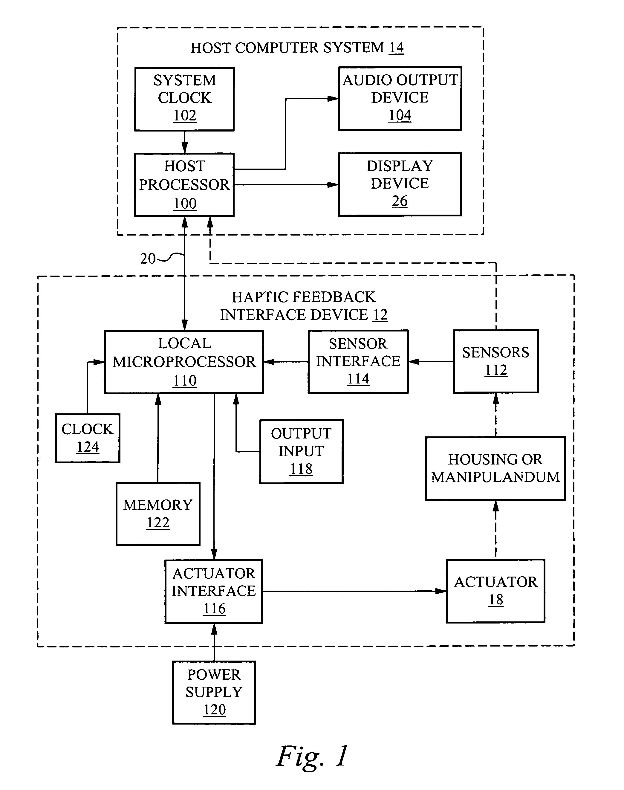
[0091]Three general types of haptic feedback are described in relation to the mouse embodiment 250; other types are also possible, and all may be implemented with other types of haptic feedback devices (joysticks, trackballs, steering wheels, laptop sensor pads, etc.). The three general types are button haptic feedback, inertial haptic feedback, and housing motion haptic feedback.

[0092]FIGS. 3a–3c illustrate generally the output of haptic feedback on a button. Button haptic feedback can be provided in several different ways. In FIG. 3a, the EAP actuator is used to provide haptic feedback and actuate motion of a button 256 in the button degree of freedom as shown by the arrow, i.e., in the direction of clicking or moving the button, where the button can be moved to another position as indicated by the dashed lines. The EAP structure (not shown) can, for example, be directly coupled to the button or be coupled to the button via a transmission or intermediate member (spring, flexure, e...

embodiment 590

[0116]FIG. 13 is a side elevational view of a braking embodiment 590 for a rotating disk. Disk 592 rotated about axis C. A caliper 594 is positioned at one end of the disk, and an EAP actuator 596 is coupled to one end of the caliper. The EAP actuator can be moved linearly to move a brake shoe 598 against the spinning cross-sectional surface of the disk, thus causing frictional resistance to the disk. A brake shoe 600 can be positioned on the other end of the caliper 594, opposite the brake shoe 598. The disk can be coupled to a variety of objects, such as a joystick handle or mouse, a rotating finger wheel or knob, or a rotating axle in a vehicle.

[0117]A stylus-shaped interface device can also be provided with an EAP actuator to produce haptic feedback to the user of the stylus. A stylus can be used to point to or select objects on a screen, or draw or write lines by contacting the stylus with a tablet or with a display screen surface, e.g. on Personal Digital Assistants (PDA's), t...

embodiment 620

[0118]FIG. 14b shows a different embodiment 620 that causes a front end portion 622 of the stylus to linearly move with respect to the back portion 624 of the stylus. A rubber bellows 626 can be positioned between the moving front portion and the back portion, and an EAP actuator (not shown) can be positioned inside the stylus housing. The EAP actuator can be a linearly-moving element that is coupled to the front end portion 622 to move that portion similarly to moving the tip member as shown in FIG. 14a. Haptic sensations can be output to the user similarly as described with respect to FIG. 14a.

[0119]Other features of a stylus can also be actuated using EAP actuators. In FIG. 14c, a stylus 640 is shown having a button 642 which can be controlled (by a host computer or other controller) to linearly move back and forth by coupling a linearly moving EAP actuator 644 to the button as shown. The button can be actuated to correspond to interactions between a controlled cursor and other ...


PUM


Abstract

Haptic feedback interface devices using electroactive polymer (EAP) actuators to provide haptic sensations and/or sensing capabilities. A haptic feedback interface device is in communication with a host computer and includes a sensor device that detects the manipulation of the interface device by the user and an electroactive polymer actuator responsive to input signals and operative to output a force to the user caused by motion of the actuator. The output force provides a haptic sensation to the user. Various embodiments of interface devices employing EAP actuators are described, including embodiments providing direct forces, inertial forces, and braking forces.

Description

CROSS REFERENCE TO RELATED APPLICATIONS[0001]This application claims the benefit of Provisional Patent Application No. 60 / 206,929, filed May 24, 2000 by Bruce M. Schena, entitled, “Haptic Feedback Devices Using Electroactive Polymers,” and which is incorporated herein by reference for all purposes.BACKGROUND OF THE INVENTION[0002]The present invention relates generally to interface devices for allowing humans to interface with computer systems, and more particularly to low-cost computer interface devices that allow the user to provide input to computer systems and allow computer systems to provide haptic feedback to the user.[0003]A user can interact with an environment displayed by a computer to perform functions and tasks on the computer, such as playing a game, experiencing a simulation or virtual reality environment, using a computer aided design system, operating a graphical user interface (GUI), navigate web pages, etc. Common human-computer interface devices used for such int...

Claims


Application Information

Patent Timeline
IPC IPC(8): G09G5/00G06F3/01G01D7/00G05G9/047G06F3/00G06F3/033G06F3/0484
CPCG01D7/007G05G9/047G06F3/016G06F3/0338G06F3/03545G06F3/03547G06F3/0362G06F3/03543G05G2009/04766G06F2203/015G06F2203/013
Inventor SCHENA, BRUCE M.
Owner IMMERSION CORPORATION
Why Eureka
Try Eureka