Variable-motion optical tomography of small objects

a technology of optical tomography and variable motion, applied in the field of optical tomography (ot) imaging systems, can solve the problem that the design of the optical tomography does not address the more general problems

Inactive Publication Date: 2007-03-27
VISIONGATE
View PDF59 Cites 29 Cited by
  • Summary
  • Abstract
  • Description
  • Claims
  • Application Information

AI Technical Summary

Benefits of technology

[0003]In one embodiment, the present invention provides a method for variable-motion optical tomography (VOT), wherein motion of an object of interest, such as a cell, has a variable velocity relative to the light path that can be varied on a cell-by-cell basis. Cell velocity is controlled in one example by packing cells into a capillary tube, or any other linear substrate that provides optically equivalent 360 degree viewing access, so that the cells are stationary within the capillary tube, while the capillary tube is translated and rotated mechanically through an optical tomography reconstruction cylinder. The capillary tube motion may advantageously be controlled in a start-and-stop fashion and translated and rotated at any velocity for any motion interval, under the control of a computer program.

Problems solved by technology

The FOT design does not address the more general case where cell velocity and / or direction of motion are variable.

Method used


Image

  • Variable-motion optical tomography of small objects
  • Variable-motion optical tomography of small objects
  • Variable-motion optical tomography of small objects

Examples


Embodiment Construction

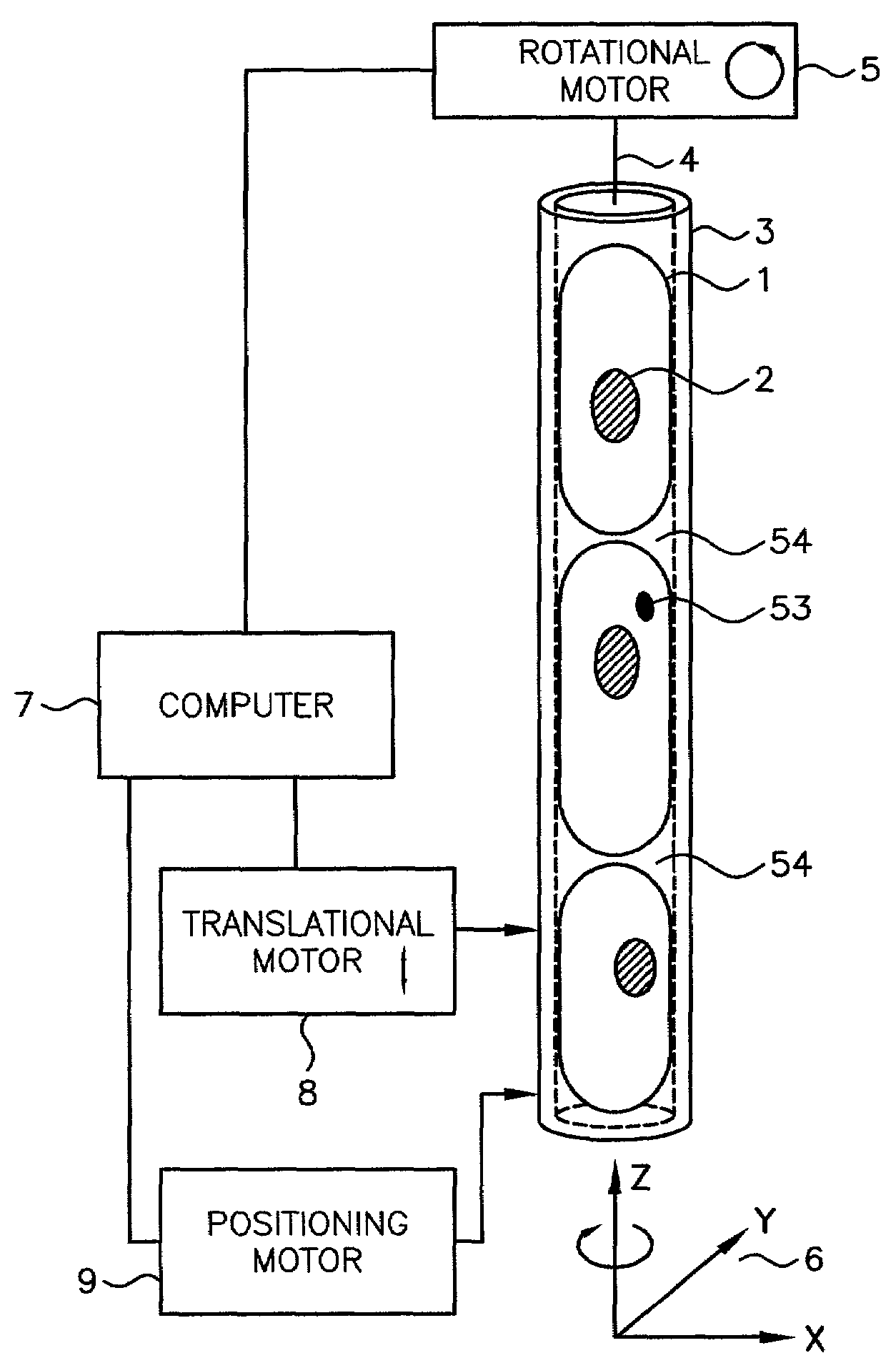
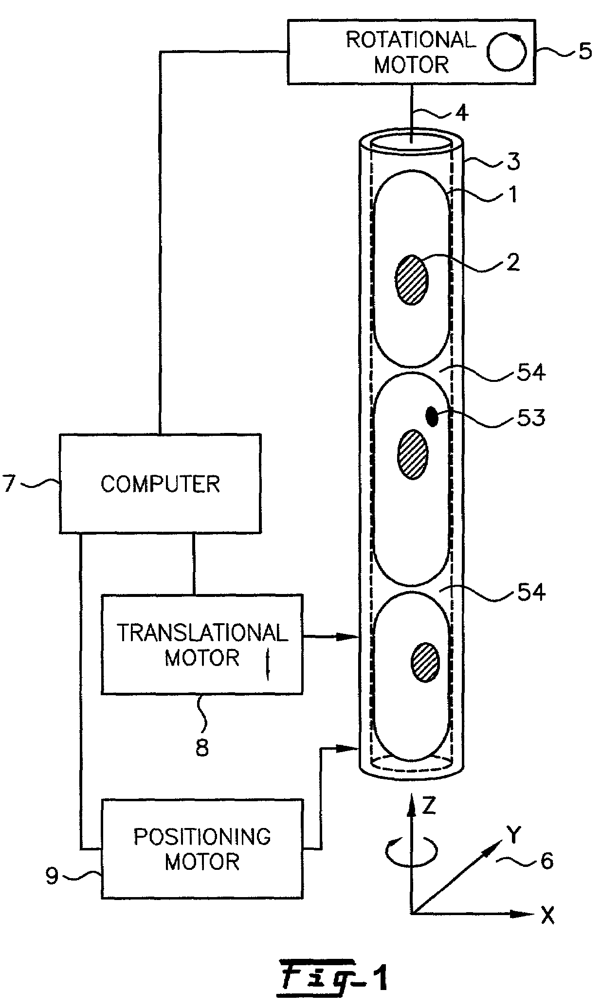
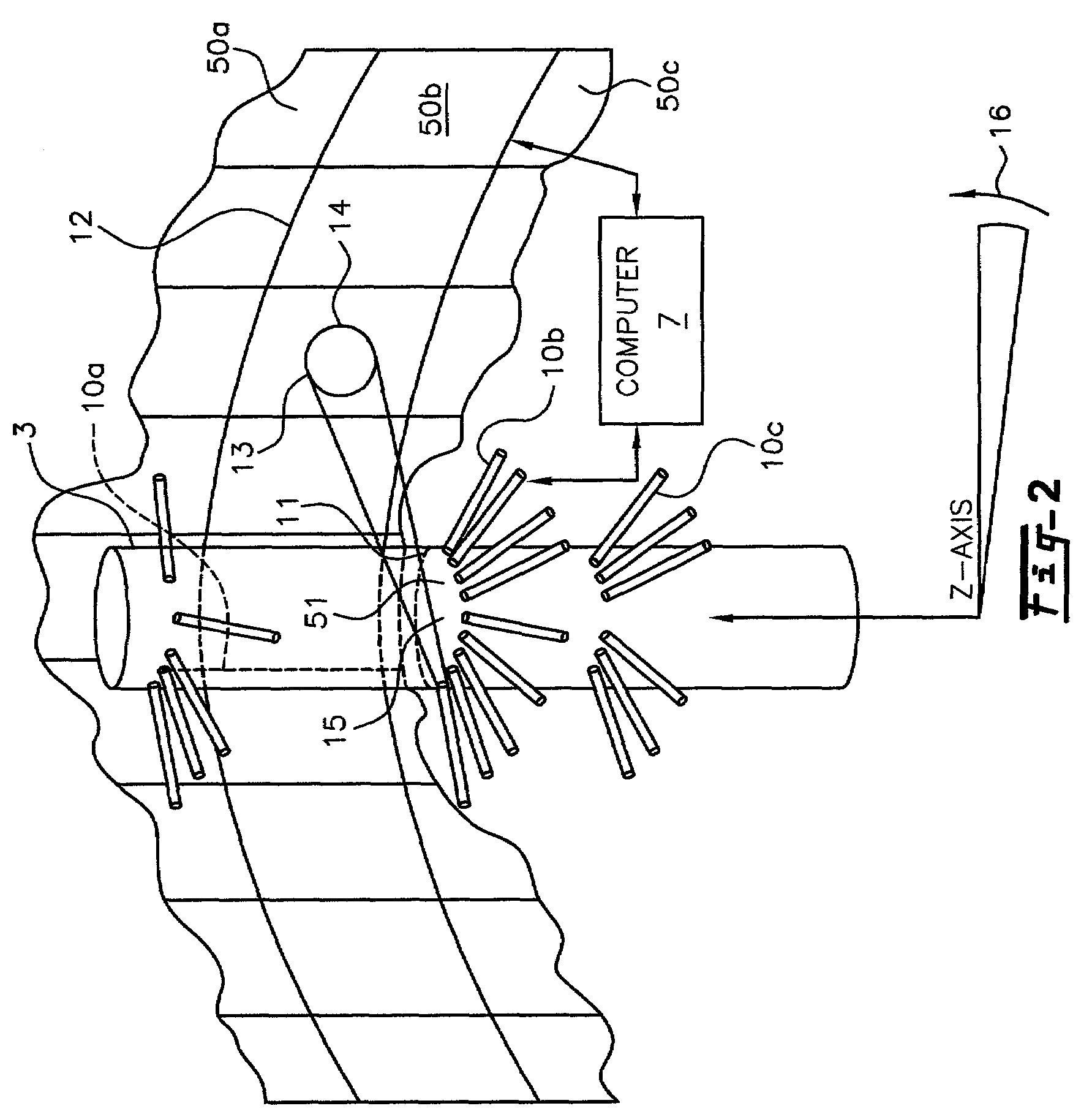
[0009]The invention is described herein with respect to specific examples relating to biological cells, however, it will be understood that these examples are for the purpose of illustrating the principals of the invention, and that the invention is not so limited. In one example, constructing a three-dimensional distribution of point densities and emission intensities within a microscopic volume allows the measurement of density and fluorescence at any location within the microscopic volume and determines the location of structures, molecules or molecular probes of interest. By using tagged molecular probes, the quantity of probes that attach to specific structures in the microscopic object may be measured. For illustrative purposes, an object such as a biological cell may be labeled with at least one tagged molecular probe, and the measured amount and location of this probe may yield important information about the disease state of the cell, including, but not limited to, various ...


PUM

PropertyMeasurementUnit
diameteraaaaaaaaaa
diameteraaaaaaaaaa
lengthaaaaaaaaaa

Abstract

Motion of an object of interest, such as a cell, has a variable velocity that can be varied on a cell-by-cell basis. Cell velocity is controlled in one example by packing cells into a capillary tube, or any other linear substrate that provides optically equivalent 360 degree viewing access, so that the cells are stationary within the capillary tube, but the capillary tube is translated and rotated mechanically through a variable motion optical tomography reconstruction cylinder. The capillary tube motion may advantageously be controlled in a start-and-stop fashion and translated and rotated at any velocity for any motion interval, under the control of a computer program. As such, there are several configurations of the optical tomography system that take advantage of this controlled motion capability. Additionally, the use of polarization filters and phase plates to reduce light scatter and diffraction background noise is described.

Description

FIELD OF THE INVENTION[0001]The present invention relates to optical tomographic (OT) imaging systems in general, and, more particularly, variable-motion optical tomography (VOT) where the motion of a small object, such as a biological cell, for example, is controlled by a mechanical motion system whose motion is not necessarily constant and / or unidirectional, but may be variable and multi-directional.BACKGROUND OF THE INVENTION[0002]U.S. application Ser. No. 09 / 927,151 of Alan C. Nelson, filed Aug. 10, 2001, now U.S. Pat. No. 6,522,775 issued Feb. 18, 2003, entitled “APPARATUS AND METHOD FOR IMAGING SMALL OBJECTS IN A FLOW STREAM USING OPTICAL TOMOGRAPHY,” (hereinafter called the FOT design) is incorporated herein by this reference. In the aforesaid Nelson patent application, cell motion is accomplished in a flow stream, wherein cells in suspension move with constant velocity along the single flow axis of a capillary tube. The FOT design does not address the more general case where...

Claims


Application Information

Patent Timeline
Patent Type & Authority Patents(United States)
IPC IPC(8): A61B5/05G01N21/17A61B10/00G01N15/14G01N21/21G01N21/47
CPCG01N15/1475G01N21/4795G06T11/006G01N15/147G01N2015/1006G06T2211/421G01N2015/1445G01N2201/0813G01N2223/612G01N2015/1075
Inventor NELSON, ALAN C.
Owner VISIONGATE
Why Eureka
Try Eureka